


Every so often, we get a request for the Ak, or area factors, or for the “Free Area” for our air outlets and inlets. For many years, manufacturers published “area factors” for balancing purposes. These Ak factors are determined by measurement of indicated air velocities and measured air quantities and can be used to balance HVAC systems. For a number of reasons, these values, however, are no longer being presented. When we get these requests, the first question we must ask is “What are you going to do with the value”?
The Ak value is reported as a constant, reflecting the ratio of sensed discharge velocity to the measured air quantity. It is not based on any physical dimensional relationships. Rather, it is dependent on the type of device used to measure the discharge velocity, as well as the location and orientation of this device relative to airflows. To be effective the sensor must be held in a proscribed manner, and data averaged in a specified array of measuring points, for the factor to be accurately applied.
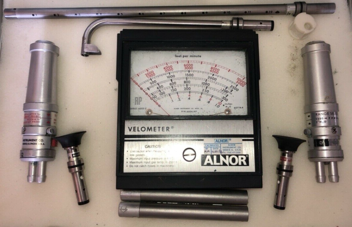
The device to be used has to be clearly specified, as the geometry of the sensor greatly affects the value observed. Early Ak factors specified the use of an Alnor 2000 Series device with a 2220A tip on the sensor. Later, the newer Alnor 6000 series device, with a 6070 tip was specified. These two devices, which are mechanical measuring devices, may yield different results when applied in an identical manner, depending on the air device being measured. The 2000 series utilized a single tube to transmit a pressure reading to a mechanical vane, connected to a gauge. The 6000 series units utilized two tubes and were typically more accurate and repeatable. The 6000 series also had the ability to measure velocities in a duct using a different type of probe tip. Both were available with extensions that allowed measurement of ceiling diffusers while standing under the outlet/inlet, without requiring a ladder. Neither of these devices, however, is commonly used at present. In the past, these devices were a single-sourced “industry standard” for balancing systems. The 2000 series device hasn’t been sold for many years, and the 6000 series has seen limited sales in recent years.
Newer electronic measuring devices, typically hot wire or hot film anemometers, while much more accurate, convenient, and portable, are highly dependent on measurement location, sensor tip geometry, and temperature sensitivity, and there is no “industry standard” arrangement. The jet of air leaving a diffuser or grille is typically a highly variable, very thin jet. The mechanical 2000 and 6000 series vane anemometers, with the appropriate sensing tips, essentially averaged the air velocity in a repeatable manner, allowing for the presentation of Ak data. The variety of hot wire geometries, usually protected by a shield to protect the sensitive film or wire, greatly affects the measurement when in close proximity to a surface. This means that while an Ak could be determined for one type of anemometer, it would not be valid for another. Additionally, most sensors must be placed parallel to the surface that the outlet/inlet is mounted in to get repeatable data. This requires a ladder for the device to be used in most applications.
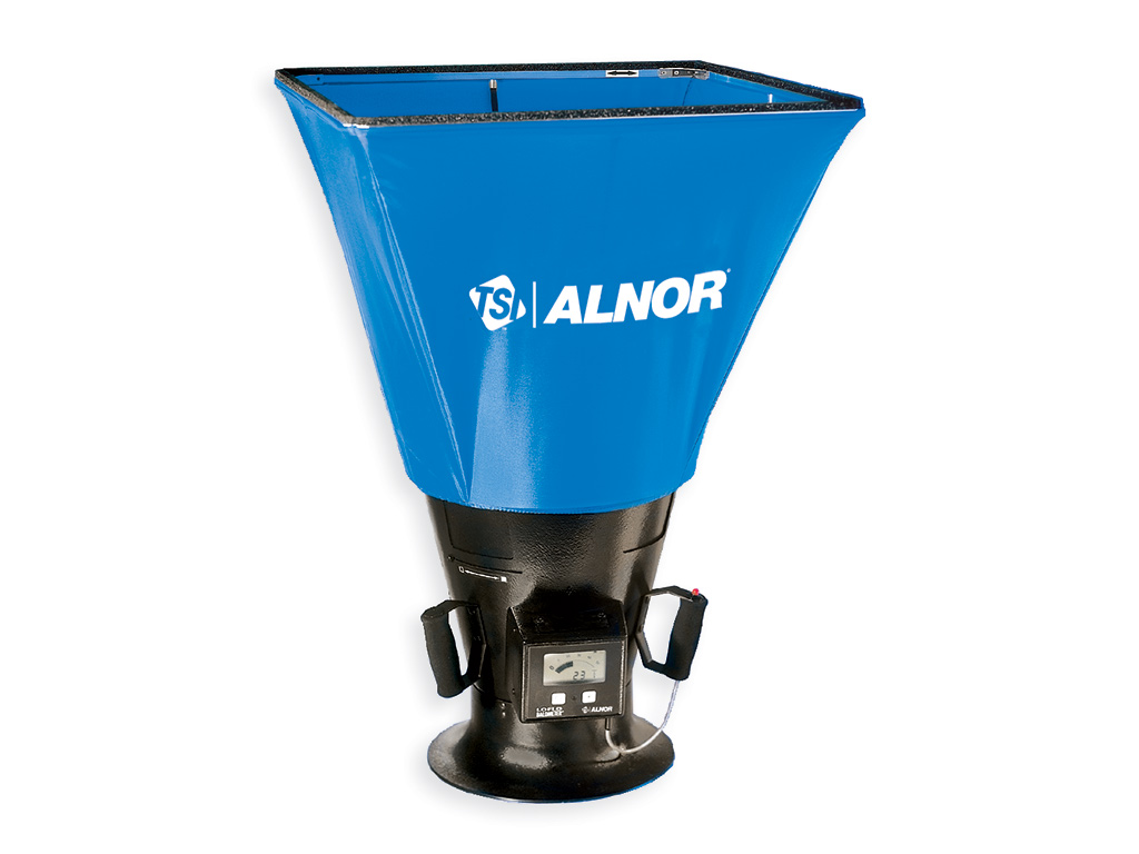
A better, and more common, measurement technique is to use a flow hood to determine airflows into and out of air outlets and inlets. Unfortunately, these are not absolute measurement instruments either. With high induction devices, such as linear diffusers, there can be significant errors between reported and actual air quantities. Differences greater than 20% are not uncommon. The most accurate technique for determining airflow quantity is a pitot traverse in a straight run of duct. This is of course seldom practical as straight runs of duct are seldom found when needed. With VAV systems employing pressure-independent VAV boxes with inlet sensors, proportional balancing with a single type flow hood can be a very effective technique. Most VAV box sensors are accurate to within 5% of the full-scale reading of the values presented on the side of most manufacturers’ products, given a relatively straight inlet to the terminal. (Note: It is highly unlikely that any VAV box sensor, from any manufacturer, is accurate to 5% of reading at minimum flow!)
In any case, the Ak factor cannot be used to determine the actual free area of an air outlet or inlet. The best way to compare actual free area between devices is to compare static pressure, or sound levels (they should be related). Blade configurations, angle, and the relationship to a specified probe location all affect the measured Ak, and may have little relationship to the actual free area. This is especially true for return grilles.
So when asked for these factors, we have to ask what the Ak value is to be used for. In most cases, we find that the balancer is attempting to determine the air quantities, and has a hot wire anemometer of some sort. When he is using one of the old Alnor devices, we may have data we can provide for many products. We find, however, that newer electronic devices seem to be the rule. We recommend the user determine his own Ak factors by carefully determining the airflow for a single device and sensor orientation, and use this on others on the project. If the user wants to use the Ak values for some diagnostic purpose, wanting to know the actual discharge air velocity, that value is not reflected in the traditional Ak values, and a better result can be had using software from the manufacturer and calculated throw data.
Until such a time as a single anemometer, and anemometer geometry again becomes a defacto “industry standard”, manufacturers cannot report area factors that can be used with any of the newer instrumentation types available.
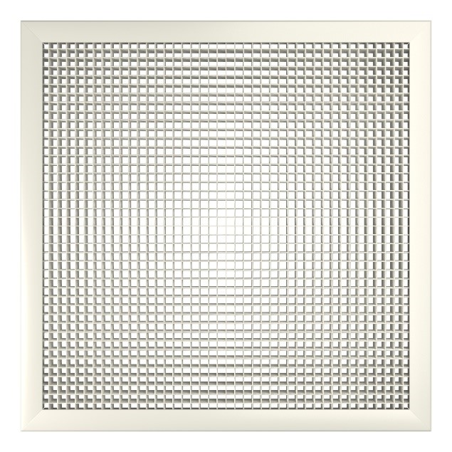
As for “Free Area”, again we have to ask “what are you going to do with the data”? For example, a metal Egg Crate grille would appear to have a lot of free area in terms of the non-metal area (hole) vs the edge of the egg crate material. In practice, however, the air will have resistance to the metal and create a “vena contracta” or stagnant area alongside the metal-reducing the actual area in which the air flows. Most ½” egg crate grilles have an “effective” free area less than 50%, and a 1” egg crate will have less than that.
So in use, the term “free area” is likely not a useful measure, except possibly for light transfer.