


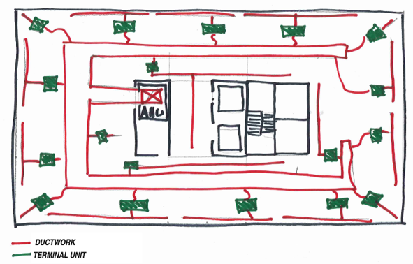
In many VAV systems, the exterior zones will utilize fan-powered terminal units. When compared to a single duct terminal unit, the fan-powered versions have a fan that enables the induction of plenum air into the airflow. During heating, the supplied conditioned air can be reduced to the minimum ventilation rate and the heating airflow is supplemented by induced plenum air. The introduction of the fan adds a few more variables to consider when selecting the equipment.
Parallel vs. Series
Before selecting the individual terminal units, the engineer will have to determine if they want to use parallel or series fan-powered terminal units. This decision has some bearing on how they select the air handling unit.
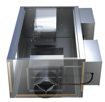
Parallel
With a parallel terminal unit, the fan is located outside of the primary airflow, i.e. the fan airflow is parallel. During cooling mode, the fan in the parallel unit is off. This requires the fan in the air handling unit to be sized such that it can deliver the full design airflow to the room. The engineer must consider the pressure drop through the terminal unit, down the ductwork, and through the air distribution devices when sizing the air handling unit fan.
During heating and dead band modes, the primary air from the air handling unit will be reduced to the minimum required ventilation rates, and the fan will be energized. Depending on the building control sequence, the speed of the fan and the amount of heat required will be modulated to meet the heating needs of the space.
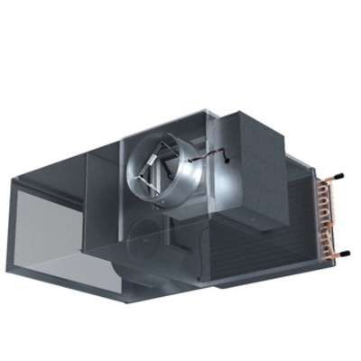
Series
 Series terminal units have the fan in series with the primary air. This requires the fan in the terminal unit to be operational when the air handling unit is on. The fan in the terminal unit will be responsible for delivering the airflow to the space, eliminating this requirement from the air handling unit. The result is less pressure load on the AHU fan, which could lead to a smaller fan and less energy used.
Traditionally these terminal units had a constant volume control sequence. During occupied modes, regardless of the space cooling/heating demands, the fan is delivering the same volume of air. The temperature of the air being delivered would be modulated by changing the amount of primary air during cooling modes and modulating heating during heating modes. Whatever air is not provided by the air handling unit will be induced into the airflow from the plenum. More modern control strategies move the speed of the fan to track the primary air during cooling, reducing energy use.
Parallel vs. Series
Each of these designs has benefits and drawbacks. The decision of what type of fan-powered affects how you design the air handling unit, so it has to be known early in the project.
-
Parallel
-
Pros
- Fan on only during deadband and heating
-
Cons
- In cooling mode, the unit is pressurized and relies on a backdraft damper to keep from leaking
-
AHU must be sized to deliver air to air distribution
- Higher pressure in ductwork could lead to higher leak rates
-
Pros
-
Series
-
Pros
- AHU fan can be downsized because it only supplies to the terminal unit
- Lower pressure on ductwork
- Unit is negative pressure, no leaking
-
Cons
- The fan must run continuously
-
Pros
Fan Powered Capacities
Let’s assume for our project that the engineer has selected Parallel Fan Powered Terminal Units.
 For the purposes of this exercise let’s choose an external zone and assume that it will be serving an open office. This space would cover the 15’ exterior zone which is 50’ wide. For an open office that is 750 sq. ft. it will provide space for 10 people. The load calculation software calculates the cooling load for the space to be 1,100 ft3/min (cfm). Based on the ASHRAE 62.1 minimum acceptable ventilation requirements for office space this room would require a minimum of 145 CFM.

The load calculations for heating in the space calculate a max heating airflow of 900 CFM at 95º leaving air temperature.
Using this information, the series fan-powered terminal unit will need to supply a max of 1,100 CFM during cooling and shall deliver 900 of heating with a minimum 145 CFM of primary air.
VAV Selection: Series Fan Powered Terminal Unit
Where the single duct units are sized using the inlet of the ductwork, a fan powered unit must choose an inlet size as well as a fan/unit size. Using the Nailor 35N parallel fan powered terminal unit catalog information we can look at the inlet size.
Inlet
Using the information above, the terminal unit must be able to supply a maximum of 1,100 cfm. Looking at the data in the catalog, the 7” inlet is too small, size 8 is right on the cusp of 1,100 and then the size 9 and 10 could be an option.
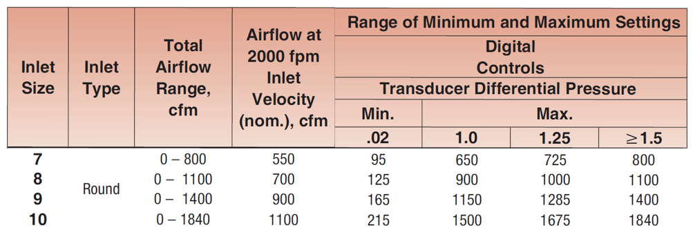
One thing to note is the minimum setting is 165 for the 9” Inlet and 215 for the 10” Inlet. This is the minimum amount of air that the flow transducer in the actuator can accurately measure. It is important to know when calculating the heating capacity needed.
Unit Size
We’ve determined that the inlet should be either 9” or 10”. Now we must choose the unit size, which is driven mostly by the size of the fan in the unit. For a parallel unit, the fan only has to deliver the max heating cfm minus the minimum primary air. In this case it would be:

Let’s start by looking at the fan curves for a few of the sizes:
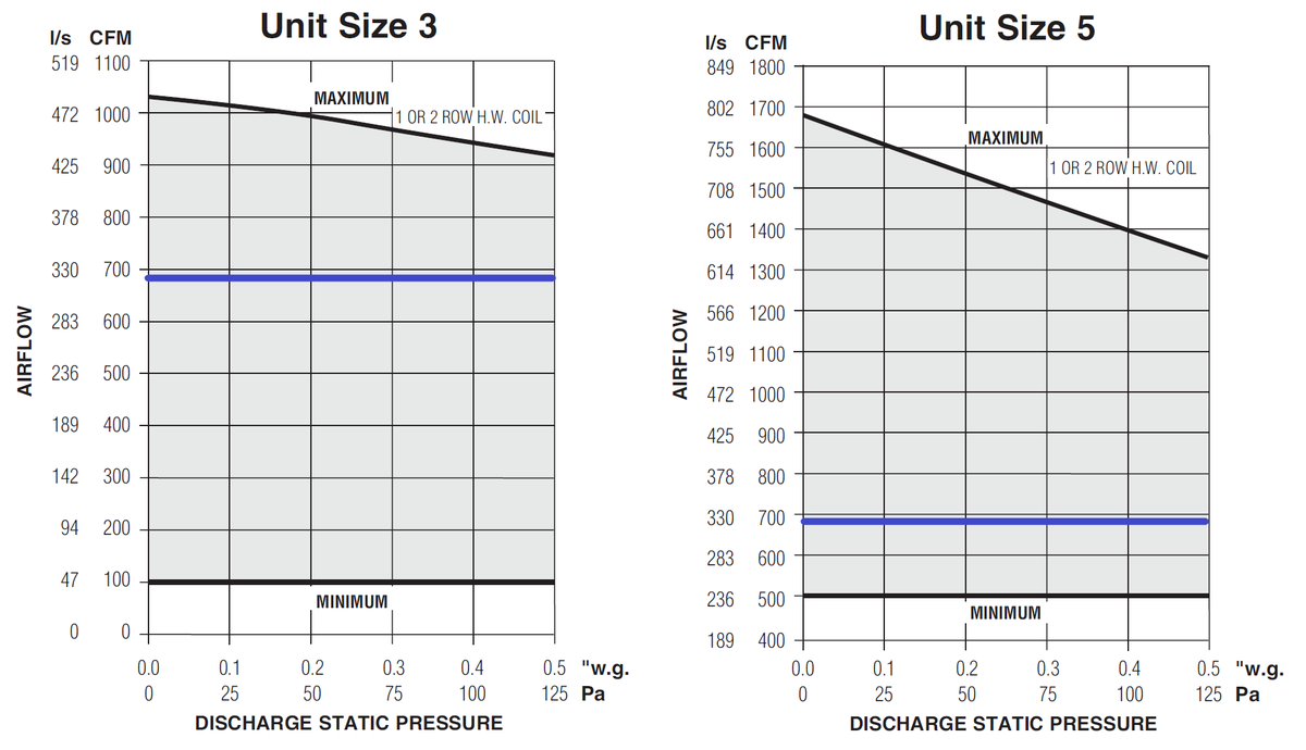
Using an EC Motor allows the controller to meet any airflow between the max and mins for the fan. For 685 CFM max, the sizes that could be chosen are the Size 3 and Size 5. Either one of these could be an acceptable selection for airflows. We next need to look at the sound data to determine if one was superior to the other.
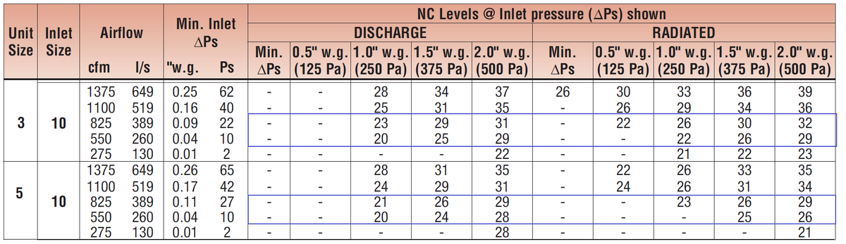
The sound data for two options Size 3-10” Inlet and Size 5-10” Inlet are shown above. The Size 3 will provide between 22 and 30 NC while the Size 5 will be similar. Most office spaces will specify a 35 NC and will experience around a 40 NC from exterior noise and general office noise generated outside of the HVAC system. Based on this criterion both these sizes would be acceptable.
Because there are no sound reasons to select the size 5 unit, the Size 3 with a 10” inlet will work for thermal and acoustical comfort.
Heating
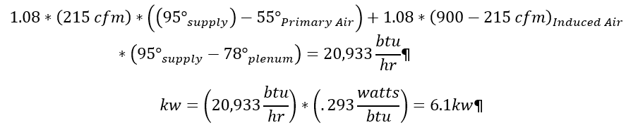
The last step will be to select the right amount of heat for the space. If we choose the size 3 with a 10” inlet, it is able to turn down to a minimum primary airflow of 215 CFM. At max heating the unit will deliver 900 CFM at 95º. To calculate the amount of heating we will use the following calculations:
Hydronic Selection
Using the total heat calculation and the heating coil charts in the catalog we can decide between the 1-row coil and the 2-row coil.
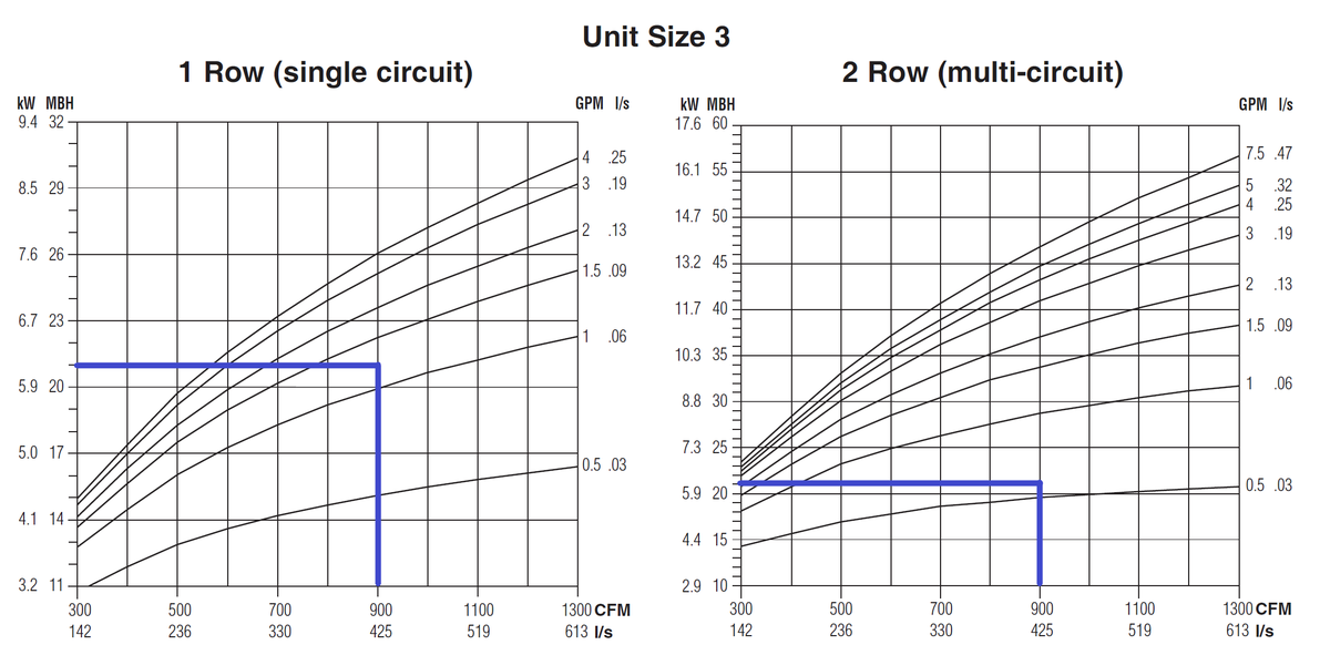
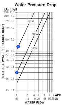 Either one of these would be acceptable, as you can see the 1-row coil requires ~1.25 gpm of hot water while the 2-row only requires ~.6 gpm. Because the 2-row is thicker the air is in contact with the coil longer so it takes less water flow to get the same amount of heat transfer. The final component of the decision is to determine how much water pressure drop is caused by each coil.
Using the chart in the catalog, the water pressure drop in the 1-row coil is 1.4 ft. H20 and the 2-row is less than 0.3 ft H20. In some systems, it may make sense to choose the 2-row coil to reduce the pump demand. Choosing the 2-row also provides some additional capacity if the heating load changes throughout the life of the building.
Electric Coil
With Nailor can provide electric heat in .1kw increments because we make our own elements. This means the engineer can specify exactly 6.1 KW for the unit. However, this would not allow for additional heating if demands on the building changed over the years. Selecting 7-7.5 KW would probably be a wise choice. The engineer will also have to determine what type of control they’d like for the heater.
Selection Software
Nailor SelectWorks software will do all these selections for you while communicating the pressure drops and electrical requirements. By entering the design conditions the software provides several options that would be able to deliver the required variables.
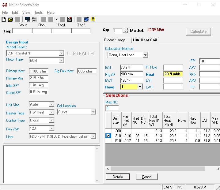
If we choose Unit Size 3 with a 10” inlet, it provides the details of this selection.
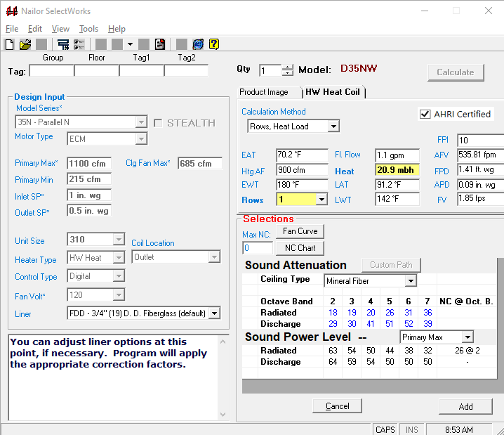
The software enables quickly going through the process described above. Nailor Sales Representatives can use this information to import into the Nailor Pricing software and quote the project quickly.
Fan Powered Terminal Unit Selection
Choosing the right terminal unit for your application can have a major impact on occupant comfort. Understanding how different options including heat, silencers, and unit size impact the performance of the system, both from a thermal and acoustical standpoint, can make a difference between a satisfied and dissatisfied occupant. If you have any questions, a project, or anything please reach out to us.