


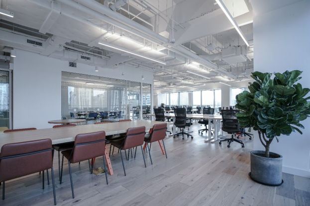
Occupant comfort is critical for the building owner’s return on investment. Chilled Water VAV systems have proven to deliver the highest level of occupant comfort, including thermal and acoustical satisfaction. Delivering comfort requires the cooperation of several pieces of equipment. When set up and controlled properly occupant satisfaction can be optimized along with the energy consumption. A major study, ASHRAE RP-1515, proved that optimizing occupant comfort coincides with a more efficient use of energy for several buildings. Understanding how the HVAC components of a VAV system work together to maintain comfort, paired with optimal set points will deliver a better system to your customer.
System Components
The equipment that work together to deliver occupant comfort in a VAV system includes the following:
- Chiller System
- Boiler System
- Air Handling Unit & Ductwork
- Ventilation System
- Terminal Unit
- Space Thermostat
The thermostat communicates the occupant’s expectation for thermal comfort. The terminal unit controls the flow of cooled, recirculated/ventilation air along with heating to maintain the setpoint. The AHU, Ductwork, and Ventilation system deliver fresh air at the right temperature as requested by the terminal unit. The chiller/boiler are required for the heat transfer: either removing heat with the chiller or adding heat with the boiler. These systems work together through the building control system to deliver a comfortable and healthy space.
The goal of this article is to introduce the operation of each system component so that in future articles we can address the details of how they work together to achieve a comfortable workplace.
Chiller System
Chillers use the refrigeration cycle to cool water to 45°F or below. The chiller system includes a series of pumps that push the water through piping to the air handling units. Within the air handling units, the water is delivered to a cooling coil. Within the cooling coil, the water absorbs heat from the recirculated/ventilation air and returns to the chiller to start over. The cooling coil also dehumidifies the air as water condenses on the cold coil.
There are two types of chillers: air-cooled and water-cooled. With a water-cooled system the refrigerant is cooled using a water loop that is connected to a cooling tower. After the refrigerant is cooled, the water is pumped through a cooling tower to reject the heat to the atmosphere, the water is cooled in the process and returned to the chiller. Water-cooled chillers are typically located indoors and the condenser water is piped outside to the cooling tower. These chillers are more efficient, have a longer life span, and are quieter than air-cooled designs; however, they’re more complex, expensive, and require additional maintenance.
Air-cooled chillers package the cooling of the water and the heat rejection to the atmosphere in the same unit. The hot refrigerant is forced through a coil, like the coil in your outdoor condensing unit, to reject the heat directly to the atmosphere. Where a water-cooled chiller works with a remote cooling tower to reject heat to the atmosphere, an air-cooled chiller is packaged directly with the heat rejection method. Air cooled chillers are located outside, require less maintenance, have a shorter life span, and are lower cost when compared to water-cooled versions.
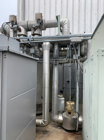
Boiler System
Boilers typically utilize natural gas to heat water for hot water heating coils. The boiler system includes pump(s) that deliver the hot water to the heating coils located in the terminal units. The hot water delivers heat to the air as it passes over the coil on its way to the space. The cooler water leaving the coil then cycles back to the boiler for reheating.
There are generally two types of boilers: conventional and condensing. A conventional boiler burns a fuel (natural gas) as water passes through tubes during combustion to heat the water. The byproducts of this combustion include water vapor. The condensing boiler passes the products of combustion across the cooler water as it returns to the boiler. This causes the water vapor to condense out of the combustion products, allowing the return water to capture the latent heat of vaporization from the products of combustion. The result is a 10-12% increase in efficiency but requires upgraded materials due to the acidic nature of the condensed combustion water. The additional costs for the condensing boiler are far outweighed by the increase in efficiency over the life of the boiler.
Piping System
There are two types of piping systems that connect the chiller/boiler to the air handling systems located near the space, these are 2-pipe and 4-pipe systems. With a 2-pipe system, the chiller and the boiler are connected to the same supply/return piping. In this case, the building can only be in cooling or heating mode at one time. With a 4-pipe system, the chiller and boiler have their own supply/return piping system. This is a more typical piping system for a commercial building, where spaces will have a diversity of heating and cooling requirements at the same time.
A 2-pipe system may be applicable in a building that utilizes electric heat for the heating of the space, eliminating the need for the boiler system.
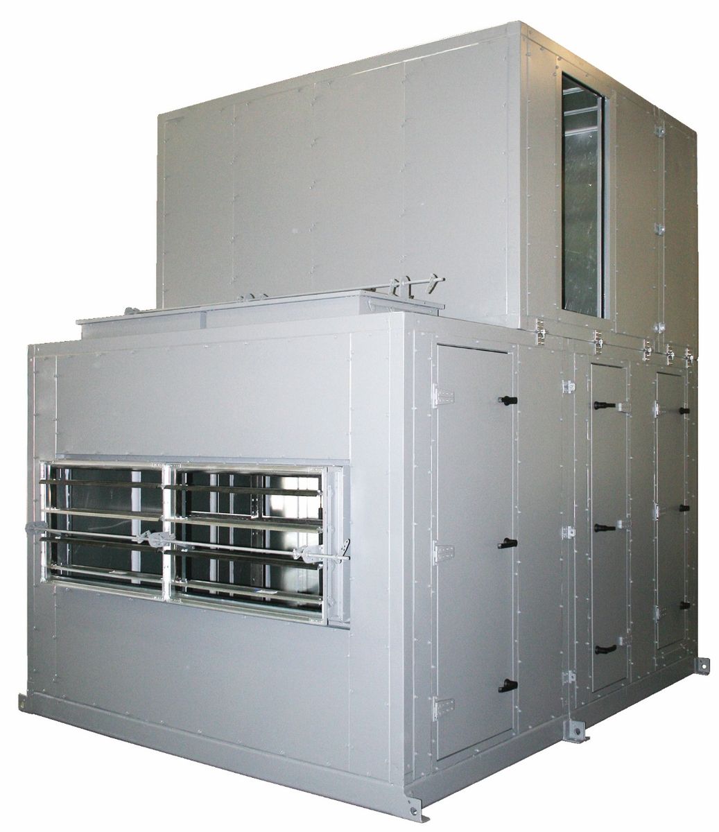
Air Handling Unit & Ductwork
The central air handling unit (AHU) of a VAV system is designed to deliver ventilation and recirculated cooled air to the terminal units. The air handling unit will typically consist of a fan and a cooling coil. In cases where there is a concern that the ventilation air will freeze the coil during winter, the AHU will have a heating coil. Otherwise, the heating will be done at the terminal units in the space.
The fan in the unit will be designed to deliver the required airflow from the mechanical room to the space. It will be controlled by a Variable Frequency Drive (VFD) that allows controlling the fan to the exact set point required by the space. For most of the AHU’s life, it will operate at part load.
The cooling coil will be designed to provide the maximum amount of cooling and dehumidification required by the space. For many systems, the AHU will be required to condition the ventilation air as well. The unit will continuously monitor the leaving air, chilled water flow, and fan speed to ensure the air being delivered stays at a constant temperature.
The ductwork connected to the AHU is the distribution network for the unit. It delivers the air to the terminal units. The AHU supplies air to the ductwork and generates a positive pressure. This pressure is monitored by the control system to help determine whether the system needs more or less air based on the load in the space.
Ventilation System
In addition to thermal and acoustical comfort, delivering fresh air to the occupants is both required and necessary for maintaining a productive space. The building codes recognized in every jurisdiction will provide a calculation based on people and/or sq. ft. of space to determine the fresh air requirements for different occupancies. Regardless of the load in the space, the VAV HVAC system must deliver the required amount of ventilation air to the occupant. With a traditional VAV system, this amount of air is delivered to the air handling unit that then distributes the fresh air to the space.
The ventilation system can include just a piece of duct that is open to the outside on one end, a fan that delivers air to the AHU, or a dedicated outside air system (DOAS) that delivers conditioned air to the AHU. For the first system, a duct leading to the outside, the AHU will be responsible for pulling the right amount of air from the outside as well as delivering conditioned air to the space. Because the amount of ventilation air is required to remain constant, regardless of the space load, the unit must have dampers that automatically control the amount of ventilation and return air so that the fresh air remains constant as the fan slows down. This is a challenge, and more than likely does not happen on many systems.
A ventilation system that includes a fan, either just a fan or a DOAS system, will be able to overcome this challenge by keeping the flow of ventilation air constant. The DOAS system will be able to deliver the air already conditioned, lowering the load on the AHU coil.
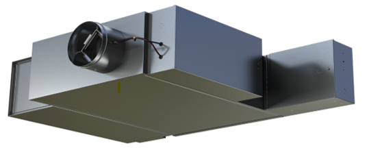
Terminal Unit
There are two types of terminal units used in commercial buildings: Single Duct and Fan Powered. The Single duct box contains a flow sensor, damper, and an optional heating coil. These are typically used in interior spaces that do not have a large heat load. The heating coil on the single duct box is needed to temper the air when the required ventilation rates exceed the demand required by the space. As technologies have progressed and lighting and equipment loads have shrunk from ~1 watt/ft2 to .2-.3 watts/ft2, the required ventilation sometimes exceeds the heat load of the space. Without supplemental heat in the interior zones, the space would be overcooled and uncomfortable for the occupant.
Fan Powered Terminal units include a flow sensor, damper, fan, and an optional heating coil. During heating, the terminal unit flow sensor and damper will work together to reduce the air flow from the AHU to the minimum ventilation requirements. The fan in the terminal unit will supply the heated airflow required to satisfy the space. To do this, the fan will induce air from the plenum to make up the difference between the amount of air required and the minimum ventilation air supplied by the AHU.
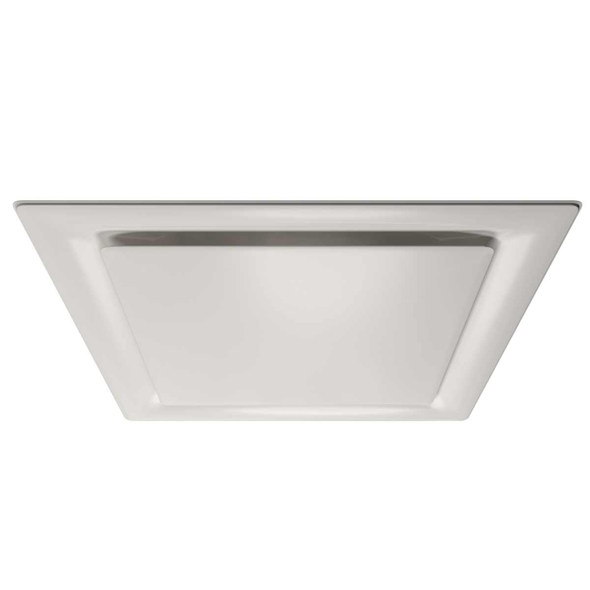
Air Distribution
Grilles, registers, and diffusers finally deliver the air to the space. The selection and design of air distribution is critical to maintaining the comfort and health of the building. Airflow within the space affect uniform ventilation, temperature, and air speeds that make up the system's ability to deliver consistent comfort control in the building.
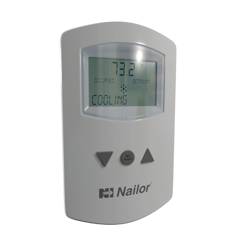
Space Thermostat
The space thermostat communicates the thermal requirement for the occupancy. Depending on the type of terminal unit associated with the thermostat, the thermostat will communicate to the system whether the space temperature meets the set point. If the space differs from the set point, the thermostat will cause the terminal unit to respond to reach the comfort setting. This alert causes responses from all the parts of the system to meet the space request.
A Team Effort
The VAV system brings together these components, and in some cases more, to deliver comfort to the occupant. The selection of each component, how they’re controlled, and how they work together to deliver comfort to the occupants can have a big impact on building performance and energy efficiency. Since comfort equals profits for the building owner, the number one reason for not renewing a lease is occupant discomfort, it is critical that this team works well.