


A mechanical engineer must consider several variables and equipment types when designing a VAV system. This includes the load on the space, the static pressure in the ductwork, the types of terminal units, and the occupancies in the space. The engineer must also consider how the terminal units are going to be controlled. These decisions must weigh the initial cost with the long-term energy efficiency. Using a theoretical office building, we will walk through the general design process and the decisions the engineer must work through to arrive at a final design.
Design Process
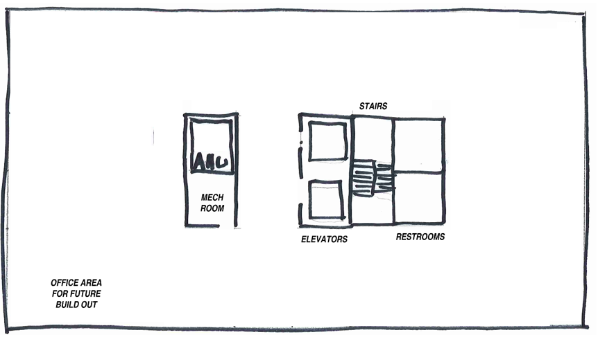
When an architect is designing a building, for purposes of this exercise an office building, they’ll start with a core and shell. The information they’ll provide the engineer will include:
- Size of building
- Orientation of the building
-
General Construction
- Window Glazing
- Insulation values
- Ceiling heights and type
- Building Use
- Sizes of mechanical rooms
Using this information, with the help of a load calculating software, the engineer will determine how much heating and cooling will be required to maintain the comfort of the building. This load will be communicated in a total amount of BTUs and then the amount of air at a certain temperature will be needed to achieve these BTUs.
Now that the engineer knows the overall demand for the space, she will use this as well as the size of the mechanical room to select the air handling unit for the space. For many VAV systems, the air handling unit will contain a cooling coil and a fan. The cooling coil will have to provide the amount of cooling with the use of chilled water. The selection software from the air handling unit will provide the engineer with the right size of coil and amount of chilled water flow necessary to cool the building. On a side note, the engineer will combine all the selections for the building to determine the total amount of chilled water required for the project to size and select the chiller for the entire project.
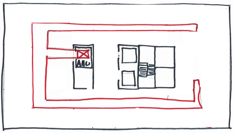
Once the AHU has been selected, the engineer will design the air distribution system for delivering the cooling to the space. This starts with the branch ductwork. To design this ductwork, the engineer will have to consider the ceiling heights and static pressure created by sizing the duct. In general, for the same air flow, larger ductwork will create a smaller pressure drop. Higher pressure drops will increase the size and amount of fan energy to deliver the airflow.
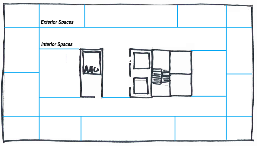
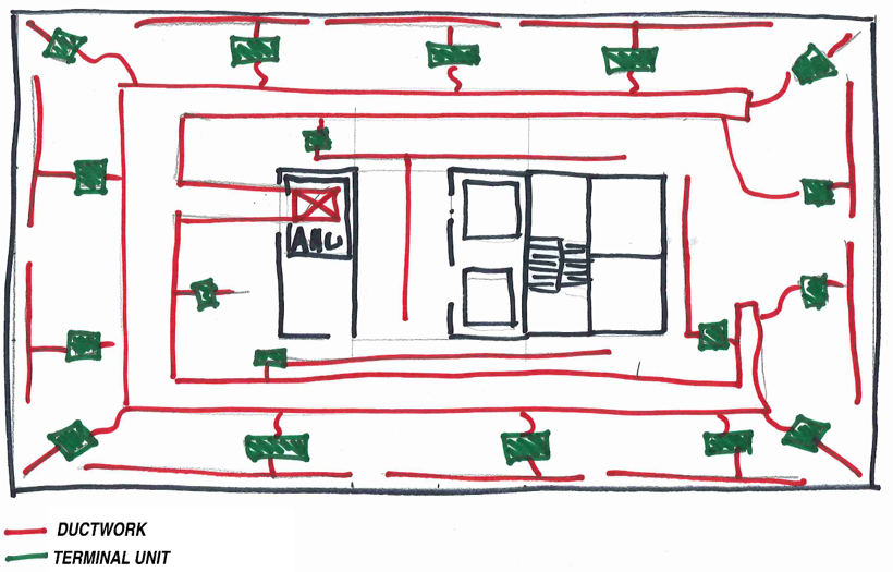
Across the floor, varied occupancies and occupants will have different needs and expectations of comfort. If we designed the air handling unit, added branch ductwork, and then tapped directly into this ductwork to serve the entire floor all in the same way some spaces would be over cooled, and others would be undercooled. In some cases, one side of the building will need cooling while the other is heating. To ensure each area has independent control over their comfort, the floor must be broken up into spaces with similar demand. During the phase of calculating the load, the engineer will break the core up into sections (as shown below). The floor will contain interior and exterior zones. When the engineer starts to design the air distribution, each one of these sections will be served by a terminal unit.
Using the loads from each one of these zones, terminal units will be selected along with the ductwork from the terminal unit needed to serve the space. Resulting in a design like what is shown below.
Terminal Unit Selections
Generally, the interior spaces will be served by single duct terminal units and the exterior spaces will be served by fan powered terminal units.
Single Duct Terminal Units
 Single Duct Terminal Units are controlled by a zone thermostat that the occupant sets to their comfort level. Depending on the temperature of the space relative to the set point of the thermostat, the terminal unit will allow less or more air from the air handling unit into the space. In some cases, the terminal unit will have supplemental heating for when the space is below the desired set point.
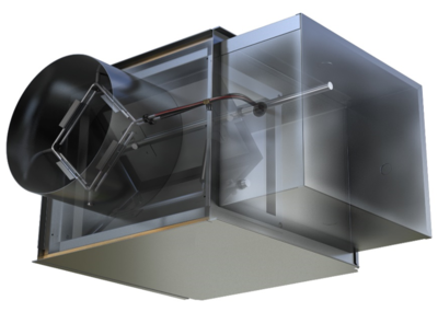
The terminal unit consist of the following components:
- Flow Sensor
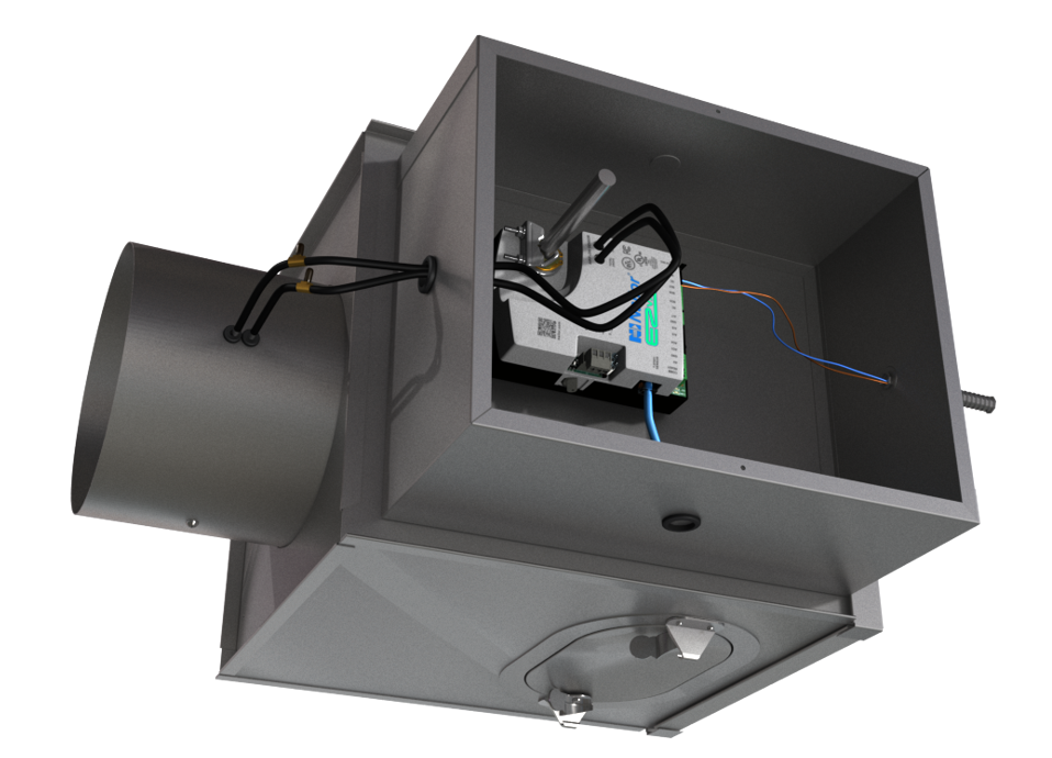
- Actuator
- Control Damper
- Heating Coil (optional)
The flow sensor makes two pressure measurements of the air flow: Velocity Pressure and Static Pressure. The front of the sensor, facing the air flow, measures the higher velocity pressure of the air flow. On the back of the sensor, facing away from the air flow, static pressure is measured. These two pressures are fed from the sensor to the actuator where the air flow is calculated.
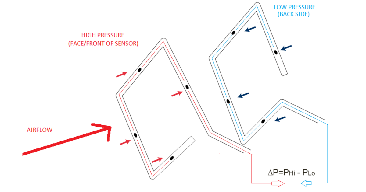
Based on the air flow, the actuator will open or close the damper to meet the comfort need of the space.
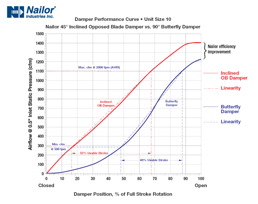
The damper opens or closes to control the airflow to the space. Nailor utilizes an opposed blade damper in our terminal units, that provides several benefits over the single blade design utilized by most providers.
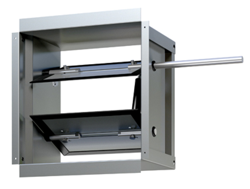
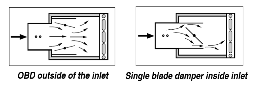
- The OBD is separate from the inlet of the terminal unit. This allows the damper to have a much lower pressure drop during operation, when compared to single blade dampers that are in the inlet. Lower pressure drop results in lower AHU fan energy and overall energy use.
- The OBD has a more linear control of the air flow. For instance, when the damper is opened 50% the airflow is 50%, this makes it easier for the unit to find the right set point when conditions in the space change.
- In single duct units, the OBD distributes the air evenly across the heating coil. With a single blade damper, the air is directed to the top and bottom of the coil, creating blast areas and reducing heat transfer.
As the energy efficiency of lighting and equipment has increased, the load in our interior spaces has drastically declined. As a result, minimum ventilation required for a space can overcool the occupants. This leads to dissatisfaction. To alleviate this, single duct units can be equipped with supplemental heating coils, either hot water or electric.
Engineers will select a specific terminal unit based on the maximum amount of primary air required, noise, and heating capacity (if necessary).
Fan Powered Terminal Units
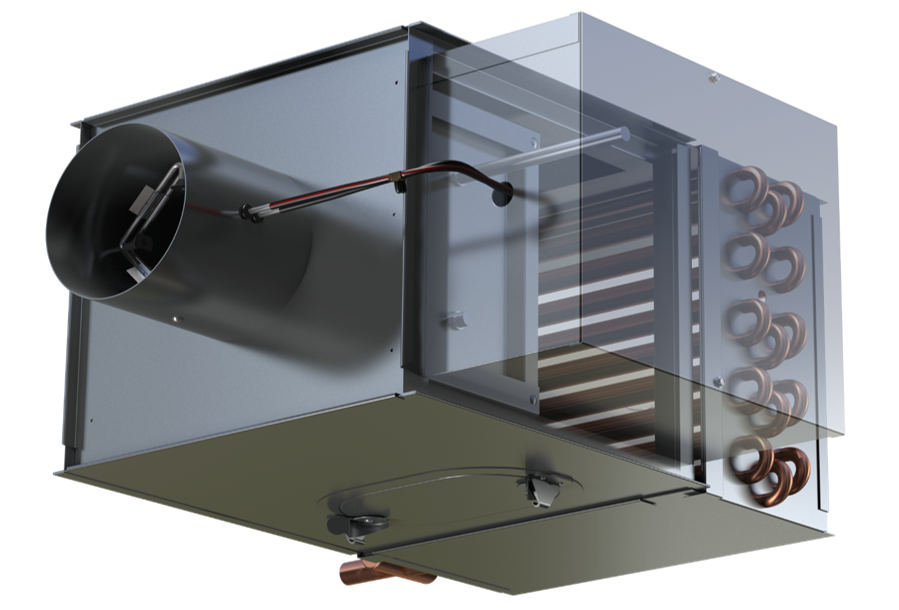
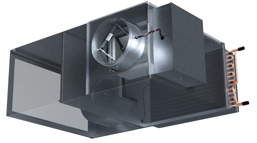
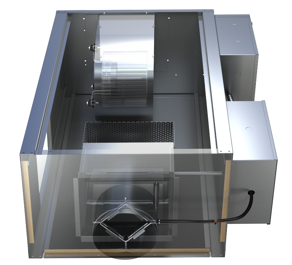
Fan Powered Terminal Units have all the same components as the single duct, with the addition of a fan. While single duct boxes have an optional smaller heating coil for supplemental heat, fan powered boxes have a larger coil (hydronic or electric) to handle higher heating loads. When the zone goes into heating mode, the primary airflow from the air handling unit is reduced to minimum ventilation rate and the fan starts to induce air from the plenum to make up for what additional air flow is needed in the space. There are two configurations for fan powered terminal units: parallel & series.
Parallel Fan Powered Terminal Units
With a parallel unit, the fan is located outside the primary air flow and when not in operation is isolated from the airflow by a backdraft damper. During cooling and deadband modes, the parallel unit acts as a single duct unit. The air handling unit is responsible for supplying the static pressure required to deliver the air to the space. In heating mode, the primary air flow is reduced to minimum ventilation rates, the fan and heating coils are engaged, and are controlled to meet the demand in the space. One challenge with the design of parallel boxes is the leakage during cooling through the backdraft damper. This typically leads to lower efficiencies when compared to series units. Some manufacturers offer the hydronic heating coil upstream from the fan, removing it from the primary air flow. While others, including Nailor, have the heating coil downstream of the fan + primary. Having the coil downstream from the fan keeps the motor from experiencing the higher temperatures caused by the coil.
Series Fan Powered Terminal Units
Series units have the fan located in the primary airflow stream. When the air handling unit is operational, the fan in the series box is also on. This allows the air handling unit to only deliver the air to the terminal units and the terminal unit fan will be responsible for delivery to the space. During cooling, the primary air flow is delivered to the unit and the series fan then delivers the air to the space. Depending on the space demand and the control sequence used, the terminal unit could be inducing some air from the plenum.
During heating, the primary airflow is reduced to minimum, the heating coil will be engaged, and the fan will pull air from the plenum to supplement the air needed to maintain comfort in the space.
Selection
Engineers will first determine if they prefer parallel or series terminal units. Once the design is selected, they’ll choose which size they need based on maximum primary air, maximum heating air, and the heating capacity. Noise is also a factor and will be part of the selection.
Delivering comfort
VAV systems are the best system for controlling comfort across a diversity of spaces. The proper design and equipment selection are key to getting it right. Nailor Industries manufactures every piece of equipment for delivering air and understands how the systems work together. With this understanding we’ve developed industry leading products that lead to the most efficient systems available on the market today.