


Choosing the right equipment for your VAV system is critical, but it is only part of creating the right solution. The specified control sequences for each terminal unit will ultimately have the largest impact on eliminating any SPACE ODDITIES. ASHRAE has issued standard control sequences for terminal units in Guideline 36: High-Performance Sequences of Operation for HVAC Systems. The goal of the guideline is to provide uniform sequences the industry can use to optimize HVAC system performance. The selection of control sequence for each piece of equipment affects the overall performance of the system.
Air Handling Unit (AHU) Control
AHUs in VAV systems are controlled using Trim and Respond control logic. A static pressure sensor in the primary ductwork that monitors pressure delivered to the system by the AHU. The system will have a static pressure set-point (SP0), minimum point (SPm), and maximum point (SPx), that direct where the unit will start and operate between. There is also static pressure trim (SPtrim), which the unit trims the supply by during TRIM operation, and static pressure respond (SPres) which the unit increases the static by during RESPONSE.
VAV Communication with AHU: Response
The individual terminal units will communicate their needs with the AHU. During operation, the damper in the terminal unit will open and close to control the temperature in the space. Once the damper is open to at least 95%, the unit will start communicating with the AHU in the following manner:
- 50% of airflow setpoint for 1 minute - send 3 requests
- 75% of airflow setpoint for 1 minute - send 2 requests
- send 1 request until the damper position is at 85%
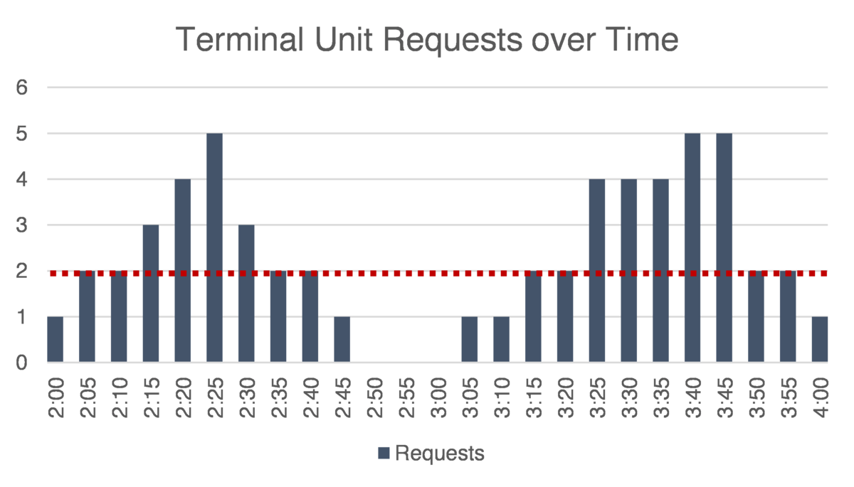
These requests from the individual terminal units are what the AHU uses to determine if a response is necessary or not. In the example given in Guideline 36, the system is set up to ignore 2 requests from the system. All things being equal, if there are only 2 requests from the terminal units then the system will continue it's trim function. If there are more than 2 requests then the system will respond by increasing the static pressure, by SPres. There is another variable response max (SPres-max) that the unit will respond with if there is an excess of requests. If there continue to be more than 2 requests, in this example, the unit will increase the pressure in the ductwork until SPx (maximum setpoint) is reached.
Trim
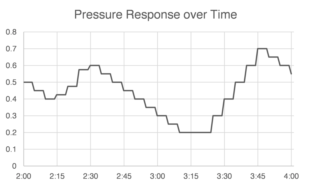
When the number of requests from the terminal units is below the number the AHU is programmed to ignore, the unit will reduce (trim) the static pressure at a set time interval. If no requests arise, the AHU will reduce the pressure in the ductwork to SPm. When requests are received the AHU will respond accordingly. Hence the name Trim & Respond. The graphs below show how the requests from the terminal units can affect the pressure (and airflow) provided by the AHU over time.
The AHU delivers the requested amount of airflow to the terminal units in the most efficient way possible. The terminal units each have their control sequences for delivering the air to the zone.
Terminal Unit Control
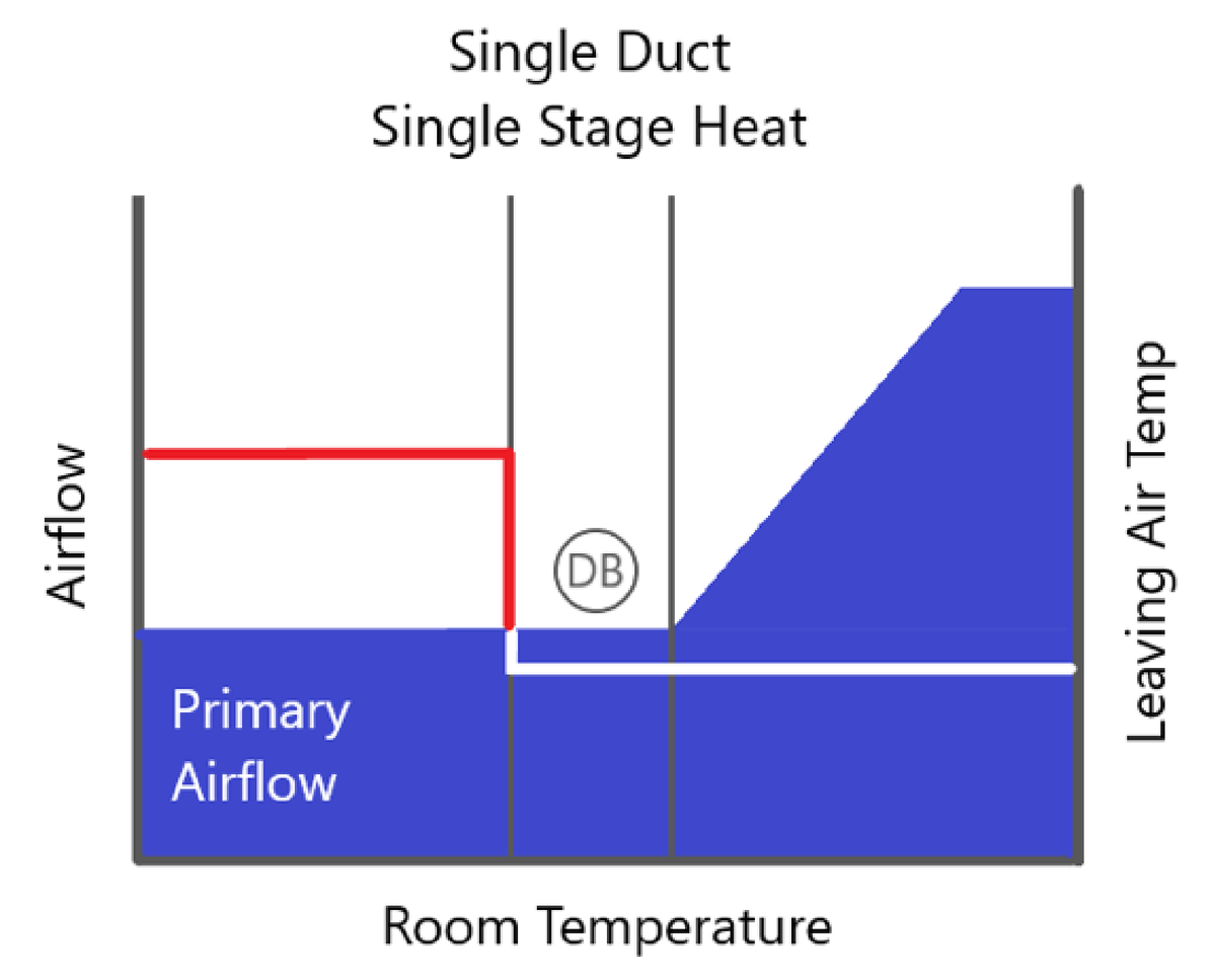
As long as the AHU is supplying enough pressure and airflow to the terminal unit such that the damper is less than 95% open, the terminal unit control will operate autonomously. The control sequences below show how the unit will control the primary airflow from the AHU (in blue), the induced air for the FPTUs in grey, and a line indicating the leaving air temperature from the unit.
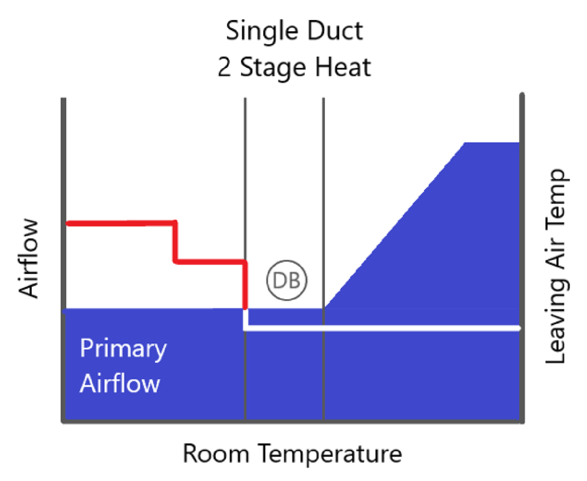
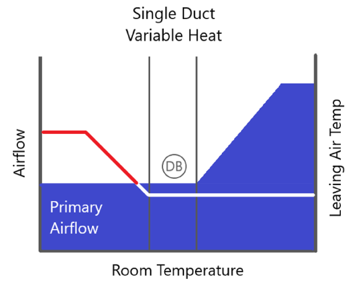
Single Duct
Single Duct terminal units control the airflow and temperature to a space with its control damper and heating coil. In VAV systems, single duct units are primarily used on interior zones. The heating coils are used to maintain occupant comfort when the minimum ventilation rate from the AHU over cools the zone.
Control of the unit is characterized by the graphics below, depending on the type of heat:
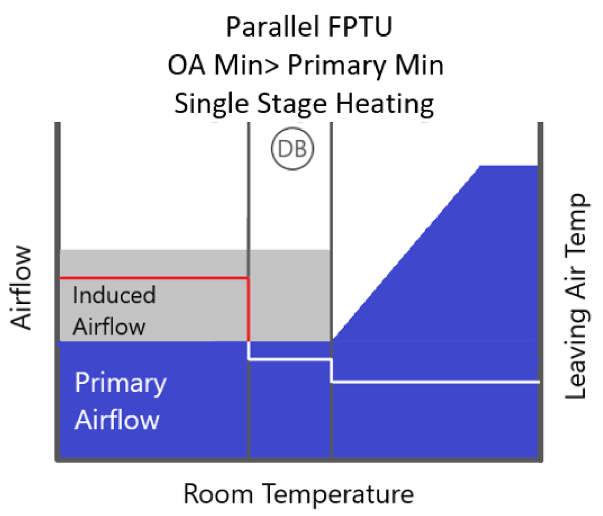
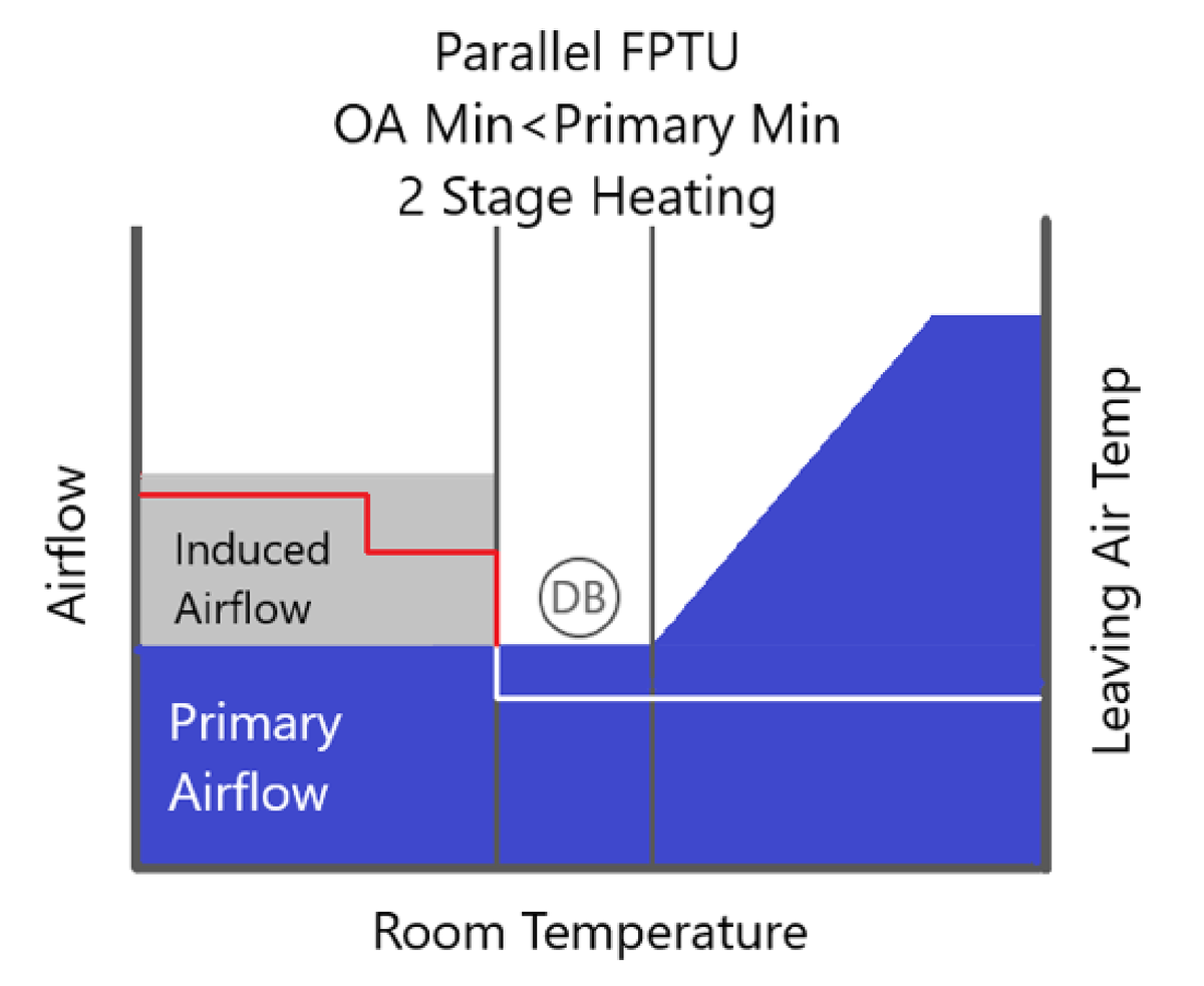
Parallel Fan Powered
Parallel Fan Powered terminal units act as a single duct box until the unit is either in heating or deadband. Based on recommendations by Guideline 36, if the OA minimum is less than or equal to the minimum primary airflow setpoint for the unit then the fan shall only operate during heating. If the minimum OA setpoint is greater than the minimum primary airflow, then the fan shall operate during deadband. The control sequences for these represented below:
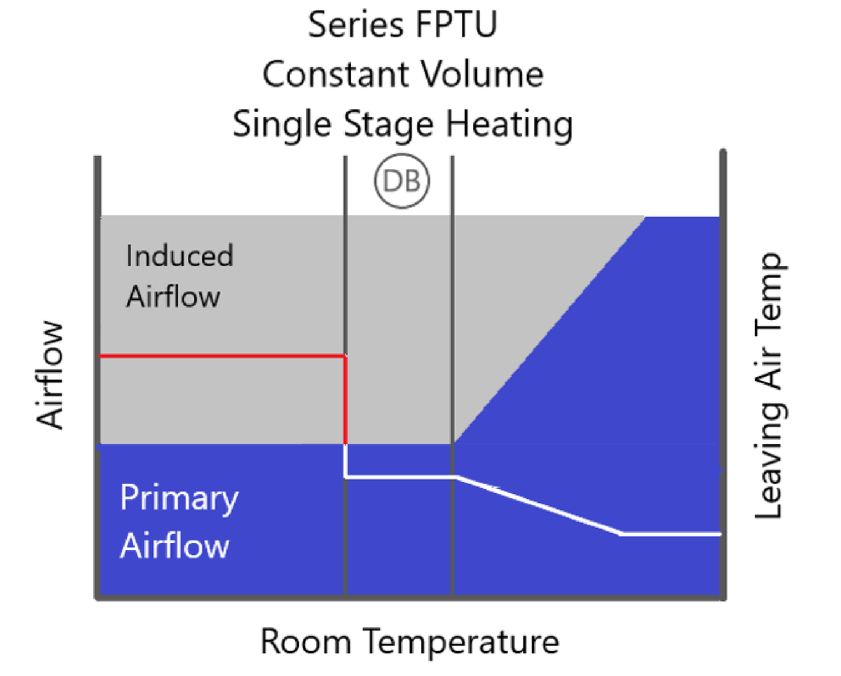
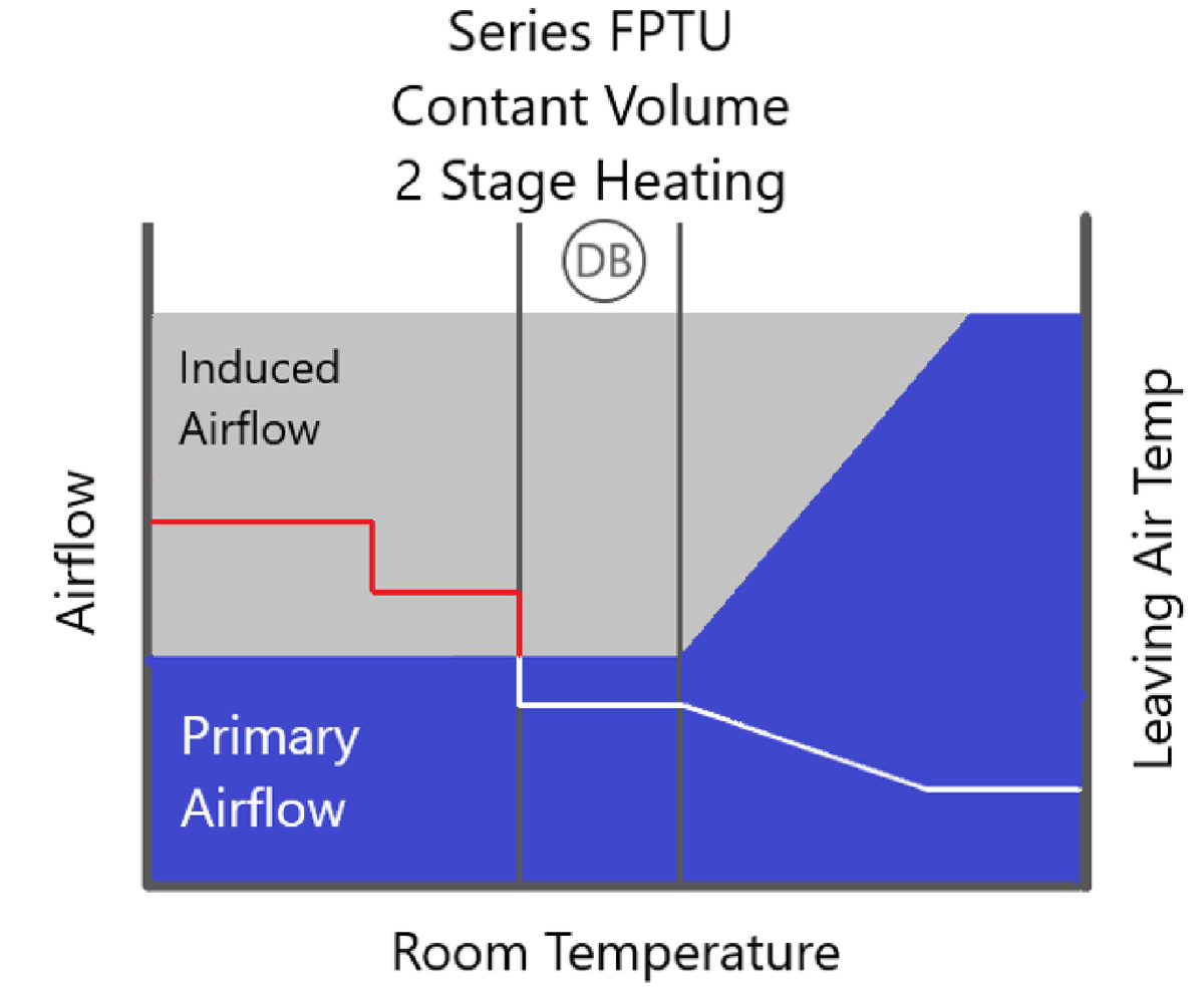
Series Fan Powered
The series fan-powered terminal unit has the fan in line with the primary airflow, it is in "series" with the AHU air. Because of this, the fan must be operational when the AHU is on. Historically these units have operated at constant volume. With this control sequence, the fan is set at a specific volume during all periods of operation. The thermal comfort in the space is maintained by modulating the amount of primary air in cooling mode and the heater during heating mode. This control was generally perceived to deliver higher comfort because it kept a constant airflow in the room and the occupant didn't experience any changes to noise or airflow. The downfall of this control is that the fan must run continuously at the same level, increasing energy use.
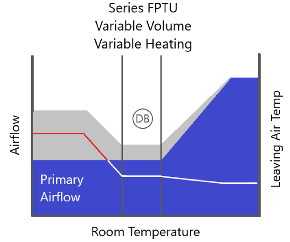
An ASHARE study published in 2014 1515-RP proved that occupants can experience higher comfort at lower airflows. To optimize comfort and energy usage, a variable volume control sequence can be utilized to deliver only the cooling required by the space. In this sequence, the terminal unit fan matches the primary airflow. Because most of the time is spent at part load and energy use is proportional to the square of motor speed, energy use is reduced significantly.
Importance of Control
Spending time to carefully select the right equipment to achieve the exact amount of comfort, performance, and or energy savings is only one part of the battle. Once the equipment is installed, the control sequences determine how they’re used, and people interact with them.