Knowing how much air is passing through a duct or entering a building is imperative in many commercial HVAC applications today but being able to control the airflow can be even more important. Throughout the HVAC industry, there already exists many innovative ways of measuring air, such as differential pressure using pitot tubes, anemometers, vortices, electromagnetic flow meters, and calculation based on damper position, yet the industry often turns to accurate and dependable Thermal Dispersion Technology. Offered as an all-in-one unit, the Thermal Dispersion Air Measuring Damper by Nailor is capable of accurately measuring the airflow using thermal dispersion probes and controlling the airflow with an actuator-modulated control damper. Featuring BACnet protocol compliance, the transmitter can communicate and be remotely monitored by a Building Automation System.
What is Thermal Dispersion?
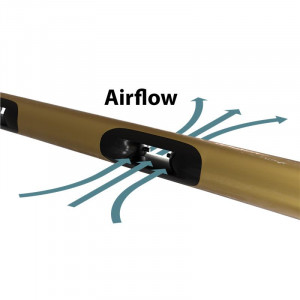
Thermal Dispersion is a principle that states that the mass flow of a liquid or gas is proportional to its rate of heat transfer. A liquid or gas will absorb heat as it passes a heating element; The more heat it absorbs, the higher the mass flow. This is detected using two thermistors, with one having an integrated heating element. One thermistor is used to determine the temperature of the air passing, while the other uses the internal heating element to maintain a prescribed temperature difference between the air and the heated thermistor. As higher airflow passes the heating element, the more it cools. The AMD-TD-XX uses electrical energy, supplying a monitored amount of current to the heating element to maintain the temperature difference. The system measures the energy it takes to maintain the difference, which is then used to determine the air flow. Using this method relies solely on temperature readings, eliminating the need for pressure and temperature correction, which is required with volumetric gas flow measurement. Having many probes in an array allow for more measuring points which give a more accurate value.
Theory and Calculation
This principle was discovered by Loui Vesso King in 1914. He conducted research that allowed him to find heat transport in flows, and how it can be related. According to Kings Law, Heat Transfer Coefficient (h) is related to Fluid Velocity (Vf) by

where a, b, and c are coefficients obtained through calibration. We must now find h. Consider a scenario in which we have a heating element (a wire) heated by electrical current input. We consider the governing equation

Where (dE/dt) is the rate of energy stored in the heating element, W is the power supplied to the heating element, and H is the heat transfer with the fluid. Assuming the scenario is in equilibrium conditions (dE/dt=0) and we have static heat transfer, we attain W=H, which can be broken down to the following:

Where I is the input current to the heating element, Rw is the heating elements electrical resistance, h is the heat transfer coefficient, A is the heating elements surface area, Tw is the temperature of the wire, and Ta is the temperature of the air. We know all the variables except for Rw, which is a function of temperature. We use the relation below to find Rw.

Combining equations (1), (3), and (4), we attain
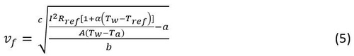
which is the equation used in finding the velocity of fluid in a duct/pipe. Knowing the size and shape of the duct, we can find the airflow CFM using

Where A is the area of the duct. The Air Measuring Damper is taking measurements continuously and performing these calculations to determine air flow. Using this information, the damper can respond accordingly to change the flow based on the settings stored in the control system.
Thermal Dispersion compared to other air measuring technology
Thermal dispersion has many advantages over other technologies such as differential pressure and anemometers. The Air Measuring Probes read actual flow rate but can also display standard flow rate using an inputted altitude value and the temperature read from one of the thermistors. Actual flow rate is the airflow of the air at that location and point in time, while standard flow rate is the flow rate at standard conditions, i.e. 0◦C and 100 kPa. Thermal Dispersion technology is also able to detect lower airflows (<300 CFM) for extended periods of time, while other technologies are not capable.
Pressure differential airflow measuring technology may use pitot tubes or traverse probes that detect the total and static pressure. They then use a relationship considered at standard sea-level conditions, which does not consider pressure and density changes that arise at different altitudes and temperatures. This outputs the standard airflow. In order to compensate, they require pressure and temperature transmitters, which adds complexity, and sensor and installation expenses. If the pressure and temperature transmitters become uncalibrated or damaged, the airflow reading could be incredibly inaccurate.
Anemometers are devices that uses the speed at which a fan spins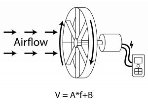
due to airflow passing through it to calculate the airflow. Though anemometers are usually handheld devices and not permanently fixed in a duct, their technology is accurate and precise. The device uses the speed at which the fan is being spun and calculates the air speed. The airflow can then be easily found using the ducts area. Although accurate, this technology requires the fan to be in the airflow, creating duct airflow and pressure disruptions. Also, it has many moving parts that can quickly wear out. Like pressure differential, this technology also requires temperature and pressure transmitters, adding some cons of the pressure differential technology. For these reasons, this technology is not used in building airflow measurement, but rather when needing to check the airflow at duct outlets in rooms.
Probes and Transmitter
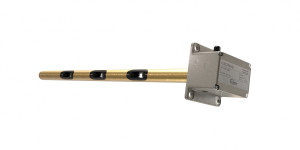
The Electra-flo G5 probes contain the thermistors that read the air and heating element temperature. The probes feature aerodynamic apertures that minimize angular flow distortion effects commonly found in ducted air distribution systems. The temperature readings are sent to a transmitter, which handles the computations and displays the desired information. Data is processed in a distributed environment,![]() which is typically done faster than in centralized data processing systems. This provides simplified wiring, which reduces costs and eliminates any redundancy. All the pre-defined parameters, such as maximum airflow, are inputted and stored in the transmitter. It converts the electrical readings from the thermistors into a temperature value, inserts the parameters into the equation from above, and finds the velocity and airflow of the air. This is being computed constantly as the probes measure the real-time airflow. In addition to airflow, the transmitter can display the air temperature and velocity. Using the inputted maximum airflow value, the transmitter outputs a user-selectable analog or RS485 BACnet or Modbus signal representing the measured airflow such that a 10VDC reading represents the maximum airflow value.
which is typically done faster than in centralized data processing systems. This provides simplified wiring, which reduces costs and eliminates any redundancy. All the pre-defined parameters, such as maximum airflow, are inputted and stored in the transmitter. It converts the electrical readings from the thermistors into a temperature value, inserts the parameters into the equation from above, and finds the velocity and airflow of the air. This is being computed constantly as the probes measure the real-time airflow. In addition to airflow, the transmitter can display the air temperature and velocity. Using the inputted maximum airflow value, the transmitter outputs a user-selectable analog or RS485 BACnet or Modbus signal representing the measured airflow such that a 10VDC reading represents the maximum airflow value.
Damper
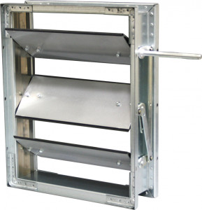
The attractive feature of the Air Measuring Damper is that it comes as a factory built and calibrated plug and play unit, minimizing field installation labor and costs. The AMD-TD-10 comes standard with a steel vee blade 1010 Control Damper, while the AMD-TD-20 comes standard with an aluminum airfoil blade 2020 Control Damper. These control dampers are used to control the airflow passing through it. The dampers are controlled by modulating analog actuators, which require a 0-10VDC signal to open and close the damper. A BACnet capable actuator is an option for those looking to automate and have more control over their buildings.
Applications
The Air Measuring Damper unit may be used in any application that requires the airflow to be measured and controlled. Common applications are outside air intake and floor supply and return tracking. For many of these applications, the contractor and rep will have to get each component separately, raising costs and increasing installation time. The Nailor Industries AMD-TD-xx is an all-in-one unit that allows quick and easy installation and set-up.
Buildings are required by Building Code ASHRAE 62.1: Ventilation for Acceptable Indoor Air Quality to maintain a healthy air quality within the buildings. To keep the quality, outside air is allowed into the ventilation system to mix with the conditioned air (air that has been conditioned many times becomes harmful to breath). The amount of air brought in must be regulated to keep a desirable ratio of outside air to recirculated air. If we have too little outside air, the air quality lessens, but if you let in too much outside air, energy is wasted in conditioning more than necessary air. For this reason, the Air Measuring Damper is excellent choice and often used for outside air intake; A fully assembled and calibrated device that can measure airflow and control it.
The amount of air flowing into a floor or room may also need the be measured and controlled. The Air Measuring Damper size ranges from 12”x12” to 48”x72”, allowing it to fit in many different sized ducts. The unit may be ordered with a honeycomb air straightener, which allows the probes to be placed in more turbulent airflows. The AMD-TD-XX can be added at any point where the air should be measured and controlled. Its BACnet capabilities allow it to communicate remotely, eliminating the need for a physical handling and reading.
Thermal Dispersion Air Measuring Dampers
The AMD-TD-10 and AMD-TD-20 are the perfect all-in-one airflow measuring and controlling station that can help automation throughout your building through BACnet capabilities and help lower usage costs by only using the correct amount of airflow. Available for many duct sizes, temperature and pressure applications, these units ensure accurate airflow measurement and control with minimal leakage. For additional information or any questions on airflow or Nailor Industries’ Airflow Measuring Dampers, please contact Kevin Del Castillo, EIT, Product Marketing Specialist, at kdelcastillo@nailor.com.