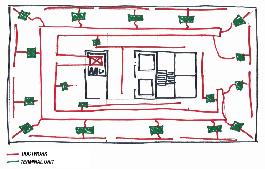
Once the building cooling/heating load has been calculated and the VAV system has been laid out, the next step is for the engineer to select the exact sizes, models, and configurations of the terminal units that will deliver the comfort to the space. For both the single duct and fan powered terminal units, several variables must be considered including unit capacities, sound, type, heating requirements & type, and manufacturer.
Single Duct Selection: Capacity
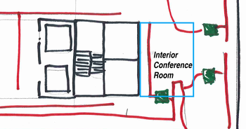
In the example office space above let’s assume that on the right side of the building there is an interior conference room that is served by a single duct box. This conference room can seat 12 people and is 240 sq.ft. in size. The load calculation software says that with people, .8 W/sq.ft. of lighting, and the equipment in the space the max cooling should be 300 ft3/min (CFM). Based on the ASHRAE 62.1 minimum acceptable ventilation requirements for an office space this room would require a minimum of 75 CFM.

The terminal unit chosen to serve this conference room must be able to deliver a maximum of 300 CFM as well as a minimum of 75 CFM.
Single Duct Selection: Sizing
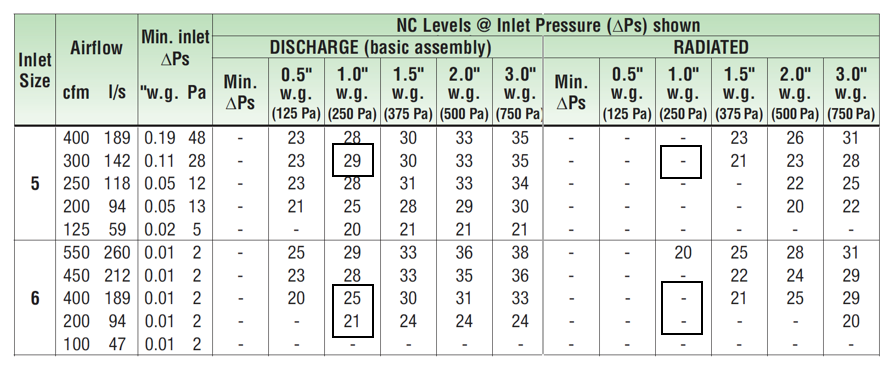
Using the Nailor 3000 series – 3001 model single duct unit as the basis of design, the catalog’d data can be used to determine the correct sizing for the application. The first few sizes for the smallest boxes have the following capabilities:
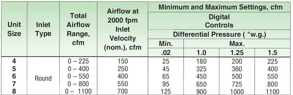
The minimum and maximum air flows through the unit are based on the differential pressure at each side of the box.
Differential Pressure
Air movement is based on a difference in pressure. The air handling unit creates a differential pressure within the ductwork to move air into the space. The ductwork, terminal units, duct connections, and ultimately air distribution equipment create a pressure drop that must be overcome by the air handling unit to deliver air. With the fan operating, as you get closer to the air handling unit the pressure in the ductwork will increase. The design of the system and selection of the terminal units must consider the pressure in the ductwork at each terminal unit. For instance, the terminal unit serving our conference room is at the end of the main duct run. This unit may only see 1.0” of differential pressure while the unit on the other side of the building, closer to the air handling unit would see 1.5”, or more.
Using this example and the information above, Unit sizes 5 and 6 would be acceptable. Both have a maximum air flow above 300 CFM (design condition) at 1.0” w.g. and a minimum airflow below our 75 CFM minimum ventilation rate. To determine which one to choose, it would be beneficial to look at the sound performance for each unit.
Sound Performance
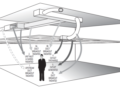
Manufacturers measure the sound created by terminal units using procedures outlined by ASHRAE Standard 130. There are two sound measurements made, one for radiated sound and the other for discharge sound. Radiated sound is the noise created by the terminal that escapes the casing of the unit. This is tested at certain airflow points in a reverberation room with connected ductwork routed outside the room, this is an effort to just pick up the sound that is radiated from the casing. Discharge sound is the noise created by the unit that is discharged down the ductwork that eventually reaches the space through the air distribution equipment. This is measured by placing the terminal unit outside of the reverberation room and ducting it into the reverberation room. The diagram below shows all the sound paths from a terminal unit and how they reach the occupant.
 The resulting sound data is presented in two different tables, one with the raw sound power levels by octave band and the noise criteria (NC) after standard deductions have been taken for standard installations as outlined by AHRI Standard 885.
If we look at the information provided for the Nailor Models discussed above at 300 CFM we can find the following:
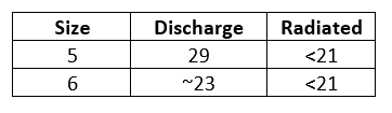
Most offices would like to design their equipment maintain a 35 NC in the space. If this is the case, both selections would be acceptable for the design. If this application was extremely sound sensitive the size 6 would be the better choice.
Though it isn’t applicable in this instance because the sound level in this application is very low, you could choose a 30RQ model that includes a 36” dissipative silencer. This silencer contains baffles made of additional fiberglass insulation surrounded by a perforated metal liner. Depending on the size of the unit the silencer can reduce the discharge sound from the unit by up to 11 NC.
Heat
The minimum airflow setting for this terminal unit will be 75 CFM. This is the minimum ventilation required to the room based on the code numbers discussed above. We all know that conference rooms are mostly used at partial occupancy, sometimes only one of two people. Because of this, there may be instances throughout the year where the minimum required cooling air over cools the space, leading to discomfort for the occupants. To combat this issue, a heating coil can be added to the unit as supplemental heat to reduce the chances of this happening. The heating coil can be either hydronic or electric.
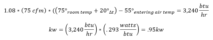
To calculate the heat load on the coil we would have to determine how much energy is required to raise the 75 CFM to 20° above the room air temperature:
Hydronic Selection
With the heat load calculated we can now view the Hot Water performance curves in the catalog to determine what size coil to order. The graph below shows the heating capacity for a size 5 30RW Terminal unit with a 1 row heating coil.
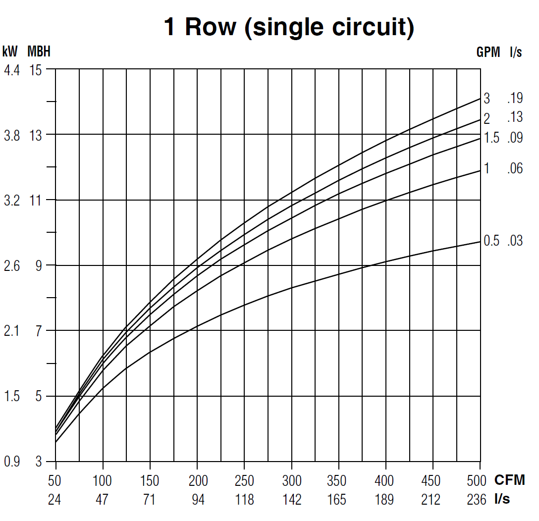
At 75 CFM a one row coil with .5 gpm of 180° F water flow would generate ~4,250 btu/hr of heat. This is more than enough to heat the space. If, in another application, the 1 row coil didn’t provide the right amount of heating, coils with up to 4 rows would greatly increase capacity. For instance, a 4-row coil for this unit with .5 gpm of 180°F water would provide 8,000 btu/hr of energy.
Electric Selection
If electric heat was chosen, based on the calculation above you would choose a 1 kw heater. Nailor offers electric heaters in .1 kw increments starting at .5 kw, allowing you to choose the exact amount needed for your application.
Selection Software
Terminal units can be selected exactly as shown using published catalogs. Most manufacturers will have a selection software that will help to do this as well. The Nailor software is called SelectWorks. The software will show you the right selection based on your conditions, this includes the size of the box and the amount of heating needed. It will also provide the sound performance data.
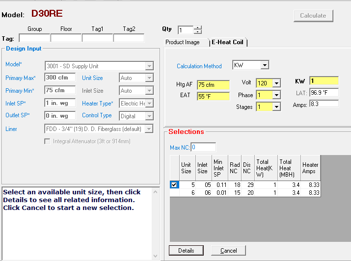
SelectWorks allows you to enter the Max/Min Airflow, Differential Pressure, and heating required. From this, it will tell you which units would meet your needs. In this instance selecting a 30RE (single duct with electric heat) it shows the size 5 & 6 units just like what we selected using the catalog. It also provides the exact leaving air temperature from the heater since we’ve chosen a 1kw heater as opposed to the exact .95kw for the calculated amount.
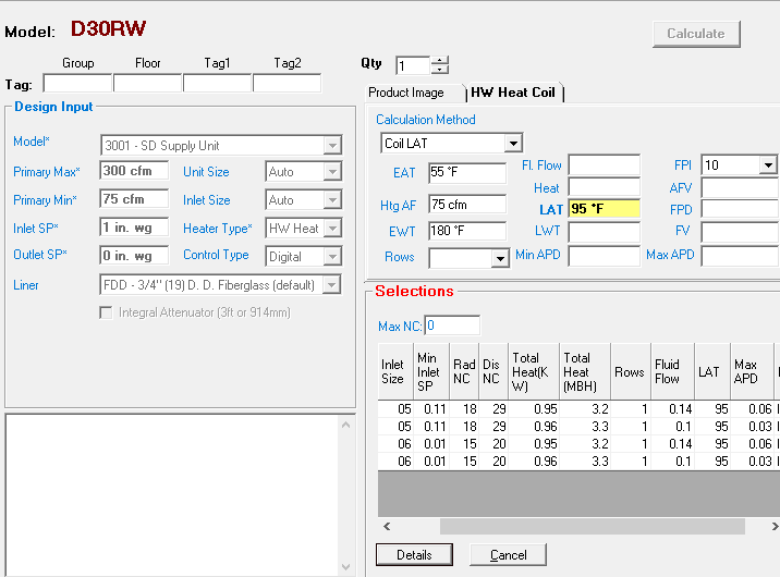
For the Hydronic Heat version (30RW) you can select the coil by several methods. I chose to enter the required leaving air temperature (LAT) and it chose a 1 row coil with .14 gpm.
The software makes it much easier to select, document, and communicate what is needed for your project. Nailor Sales Representatives can use this information to import into the Nailor Pricing software and quote the project quickly.
Single Duct Selection
Choosing the right terminal unit for your application can have a major impact on occupant comfort. Understanding how the different options including heat, silencers, and unit size impact the performance of the system, both from a thermal and acoustical standpoint, can make a difference between a satisfied and dissatisfied occupant.