The purpose of using a Variable Air Volume (VAV) system is to add controllability to a diversity of occupancies using only one air handling unit. A constant volume system is like what you have in your home, either off or on. If you apply a constant volume system to a space with multiple heating/cooling load profiles, someone will not be comfortable at different times of operation. The fundamental parts of a VAV system include:
- Air handling unit
- Primary ductwork
- Terminal unit
- The ductwork/air distribution that serves each zone
Each of these works to deliver the right amount of air to a space to control the desired temperature. More details on these components are in my VAV System Components article. It is critical to understand how the air flows through the components of a VAV system and how it is controlled to deliver comfort.
Air Handling Unit
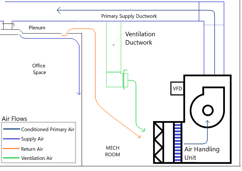
The air handling unit shown below is in a mechanical room. The fan in the air handling unit will deliver the right amount of air to the system. It is controlled with a Variable Frequency Drive (VFD) using a trim and response control sequence. This control sequence is explained in detail in a previous article located here. The air is distributed through the building via ductwork and ultimately arrives in the room as supply air through grilles/diffusers. This supply air is provided with a path to make its way back to the air handling unit as return air. The supply air passes through a return air diffuser in the ceiling into the plenum above the space. This air can then make its way through the plenum to the air handling unit. In the illustration, the mechanical room is open to the plenum. In some instances, there could be transfer ductwork.
The air handling unit also handles the required ventilation air for the space. A good VAV system will be designed such that the ventilation air will remain constant, even when the total airflow from the air handling unit reduces with the load in the space. These two airflows combine in the mechanical room and make their way through the air handling unit to start the process all over again.
Terminal Units
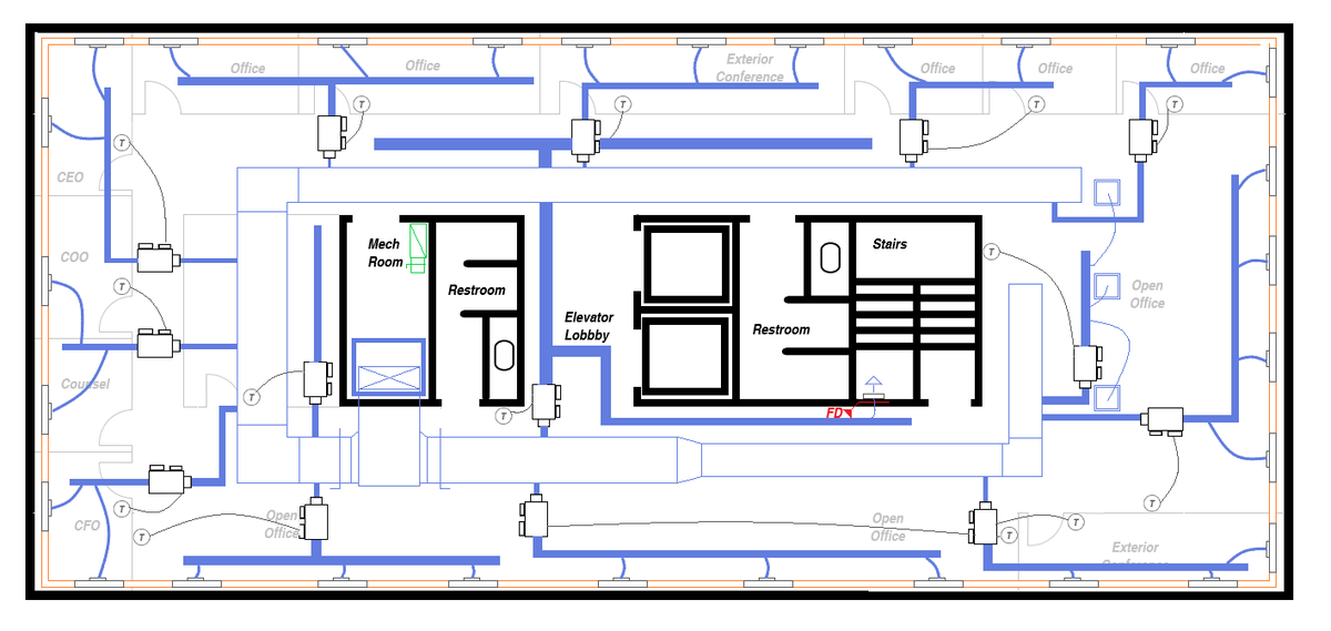
The terminal units are connected to the primary supply ductwork to control airflows to different zones. The fan and VFD in the air handling unit respond to the needs of the space to provide the exact amount of air required. Terminal unit configurations include single duct, parallel fan-powered, and series fan-powered units, each of which has different airflow profiles.
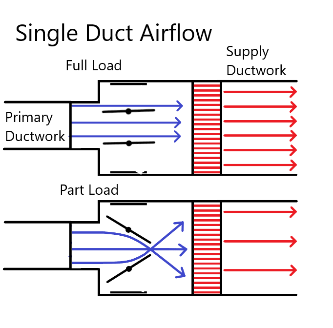
Single Duct Units
Single Duct terminal units include:
- Airflow sensor
- Actuator
- Control damper
They can also have a heating coil depending on the design of the system. The terminal unit will respond to the space thermostat to increase/decrease the airflow to maintain the set point. The Single Duct relies 100% on airflow from the air handling unit.
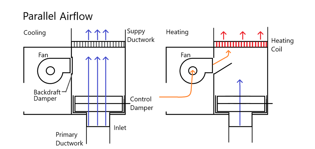
Parallel Fan Powered Units
Parallel Fan Powered units add a fan that is outside the flow of the primary air. During cooling, parallel units act the same as a single duct terminal unit. When heating is required, the primary air will be reduced to the minimum ventilation rate and the fan will operate to induce air from the plenum. The mixture of primary and induced air is then passed through the heating coil and ultimately into the space.
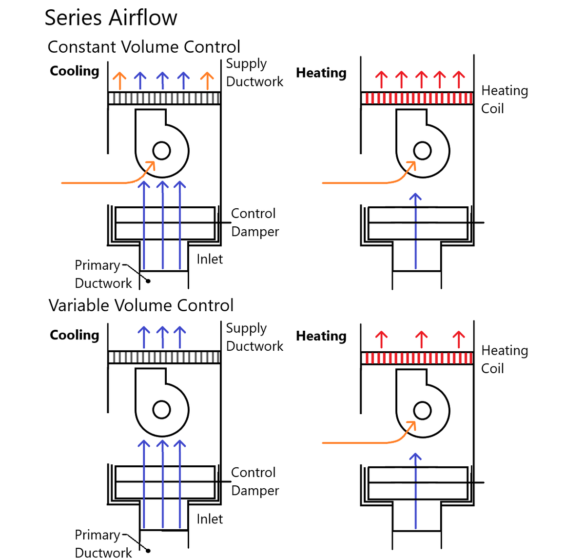
Series Fan Powered Units
Series units add a fan that is inside the flow of the primary air. As a result, the fan in the terminal unit must be operated simultaneously with the AHU. The airflow through a series unit depends on the control sequence selected.
Constant Volume
With a constant volume control sequence, the terminal unit delivers a consistent amount of air throughout the operation of the building. The amount of primary air and heating modulates in response to the calls from the thermostat. The result is constant volume, variable temperature supply. Except at max load, the fan is continuously inducing air from the plenum.
Variable Volume
A variable volume sequence has the fan match the primary airflow during cooling, resulting in very little induced air into the supply air. During heating, the primary air reduces to a minimum ventilation rate and the fan induces the right amount of plenum air to satisfy the space. The result is variable volume, constant temperature operation.
Exhaust
With a constant supply of ventilation air, there must be a means of relieving the pressurization caused by this airflow. Some of this air exhausts through the restroom fans and possibly kitchen exhaust, if applicable. The rest must be either exhausted directly or allowed to escape through a pressure relief damper. While some pressurization is good for the building, too much can have a negative effect.
Airflow
Efficient airflow through a building and a VAV system is critical to an operating HVAC system. Understanding how this equipment works together to maintain comfort in a building is critical to designing the right system for your application.