In our previous articles we highlighted the benefits, design, energy efficiency, and configurations of water source heat pump technology. Though heat pumps include a refrigeration cycle and air conditioner in one small package, they are only able to do this in cooperation with a few building systems that are critical for removing or delivering heat from/to the heat pump. To remove heat from the units the building system includes a cooling tower, and to add heat a boiler. The tower and boiler are connected to the heat pumps by a common water loop. Just like the numerous configurations of heat pump, there are several different configurations of cooling tower that can be selected for your project.
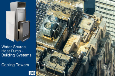
Cooling Tower
Fundamentally, a cooling tower performs the same job as the condensing unit on your split system at home. The goal is to remove heat from the building and reject it to the outside atmosphere. The difference is that the cooling tower is using water instead of the refrigerant in the split system. Also, in many configurations a cooling tower is taking advantage of heat rejection through evaporation. This allows the cooling capacity of the cooling tower to be based on the Wet Bulb (WB) temperature outside rather than the Dry Bulb (DB) which refrigerant condensing units rely on. A cooling tower’s capability is measured by how close the tower can cool the water to the atmospheric WB temperature. The difference between the cooling tower delivered water and the WB temperature is called the approach. When selecting a cooling tower, the goal is to achieve the right balance of lowest approach, cost, size, and energy use.
Parts and Operation of a Cooling Tower
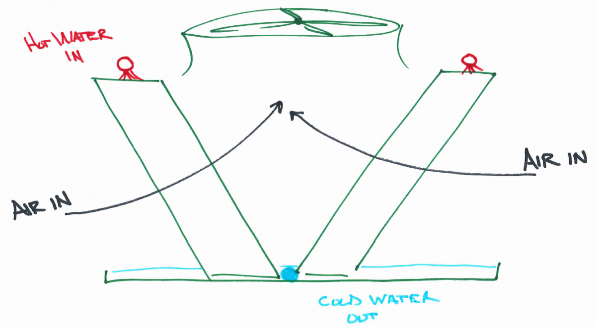
The goal of the cooling tower is to reject the heat in the water, the vast majority of which coming from evaporation. This is done by making as much of the water encounter the outside air as possible. To achieve this, all cooling evaporative towers include a fan, water inlet and outlet, and fill. The fan draws or directs the outside air through the fill in the tower. The water is pumped to fall through the fill and the fill’s job is to spread the water out to ensure the greatest surface area of the water can be achieved to increase contact with the air. As the water evaporates, it rejects energy (heat) to the atmosphere cooling the remaining water that falls to the bottom of the tower. Once cooled, the water is pumped to the next stage in its use.
Air Vs. Water Flow
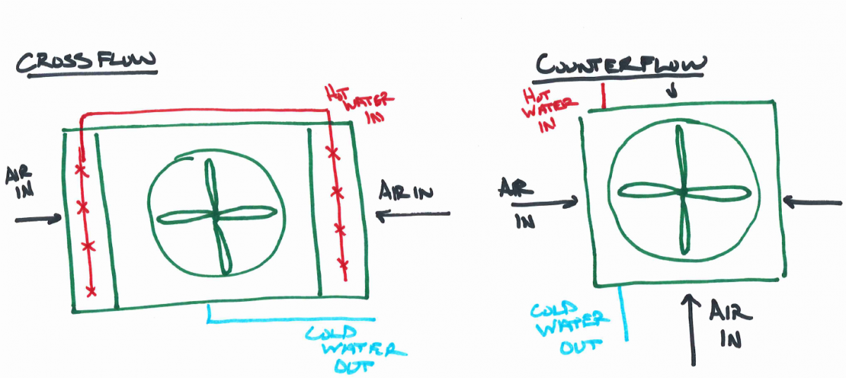
One of the largest ways to classify different cooling tower designs has to do with the direction of the air with respect to the direction of the water. The two major designs are crossflow vs. counterflow. With a crossflow design the water is pumped to the top of the tower into a basin. The basin contains holes that distribute the water flow across the top of the fill. Gravity pulls the water through the fill downward. The fan, located between the two sections of fill, draws the outside air through the fill horizontally before pushing it upward. The flow of the air and water are perpendicular, hence the name cross flow.
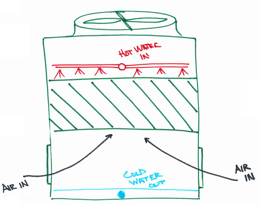
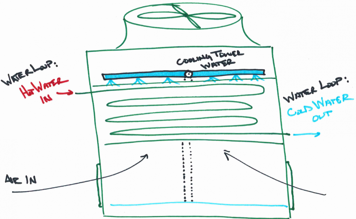
The other air flow/water flow combination is counterflow. With this configuration, the hot water is pumped up to the top of the fill and distributed via pipes with nozzles that spread the water across the fill. The fan above the fill draws air up through the fill in the opposite direction of the water flow, hence counterflow.
Which do I choose?
The selection between crossflow and counterflow mostly comes down to space requirements. For systems up to 700 tons, the counterflow design requires a smaller ground space than the cross flow. Because the counterflow design pulls air from all four sides, it can handle more air in a smaller footprint than counterflow.
Though the counterflow has a smaller footprint, it also is all packaged into smaller spaces. This makes servicing the counterflow units more difficult than the crossflow towers.
The crossflow design distributes and delivers the water to the fill mostly using gravity. The water is delivered to a basin that has holes and nozzles that the water in the basin falls through to be distributed onto the fill. The basin has many holes, for instance in one design a 400-ton cross flow cooling tower has 260 nozzles. This many nozzles require very little pressure for the nozzle to distribute the water across all the fill. This allows for even distribution of the water in the fill even at very low water flows.
The counterflow design uses pressure to distribute the water through a series of pipes and nozzles, this requires additional pumping energy when compared to the crossflow design. This design uses pump pressure and the nozzles (less than 25% of the nozzles compared to the crossflow design) to evenly distribute the water across the fill. In a variable speed situation, lower flow in a counterflow configuration can leave part of the fill un-wetted, reducing the efficiency of the tower. Without modification to the nozzle design, the counterflow design can handle 50% turn down while the cross flow can go up to 70%. Depending on the location of the cooling tower, the additional 20% turn down on the crossflow could be a significant energy savings that can’t be overlooked.
Open vs. Closed Loop Cooling Towers
Another way to classify cooling towers is if the building water loop is exposed to the atmosphere or not. An open cooling tower, like what is shown above, takes the building water and distributes it directly onto the tower fill to expose it to the outside air. Once it falls to the basin at the bottom of the tower, it is then circulated back into the building for use with the heat pumps in the system. These are considered open systems because the building water loop is open to the atmosphere.
A closed loop tower keeps building water loop contained within pipes as it is routed through the fill section of the cooling tower. The closed loop cooling tower has a water circulation system that pumps water from a basin at the bottom of the tower up to be sprayed onto the closed loop piping that the building loop is pumped through.
Which do I choose?
A closed loop system typically requires less maintenance because the building water loop is isolated from the atmosphere and therefore requires less cleaning and treatment. An open water system will require chemical treatment and the system will have to be watched closer to keep debris from hindering the operation of the system.
Due to the addition of the heat exchanger piping and additional pumping system for the cooling fluid, the closed loop cooling tower has a higher first cost. Though, operational costs of the closed loop will be less than the open system.
The closed loop system provides some additional operational flexibility. On days where the outdoor temperature is favorable the system can be run dry without the condenser water or with variable pumping on the condenser water loop when less is needed. All of which reduce the amount of energy needed to run the building.
Cooling Tower Selection
Understanding the different configurations and how they affect the system is critical to making the right decisions. Selecting the right cooling tower for a water source heat pump project depends on up front costs, operational costs, performance, ground space, and the location of the project. There are many more decisions than just these that go into choosing the right solution for your system, coordinating with the cooling tower providers and their selection software will be able to provide more detailed information. Nailor, through the Engineered Comfort brand is now providing water source heat pumps that have been designed from the ground up to deliver the most optimized portfolio of products available today. If you have more questions please contact us.