Summary
Adding a filter that has greater efficiency than just a throwaway fiberglass filter can be done but could require modifications to the unit. Each individual unit’s size, design, and operating environment would have to be considered to determine the right route to take to ensure the performance of the unit is not compromised by the addition of the filter. Also, this analysis was done considering the initial pressure drop across the filter. As the filter is used and becomes “clogged” with filtrants the pressure drop will increase. This must be considered for replacement schedules depending on how much static pressure you have with the design of the unit.
Additional consideration would have to be given to the cost and potential problems associated with the requirement to change filters regularly if filters are added to the terminal units including:
- Access to the filter above the ceiling.
- Items below the access point, including desks, office furniture, and equipment that should not be exposed to the filter changing operations
- Floors and the required clean up after the ceiling is replaced
- Damaged Ceiling tiles
- Cost of labor and filters associated with this process
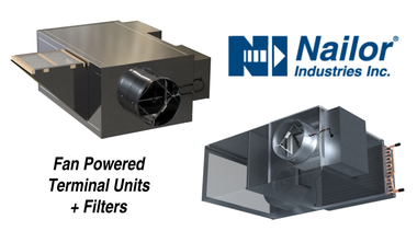
Fan Powered Terminal Units
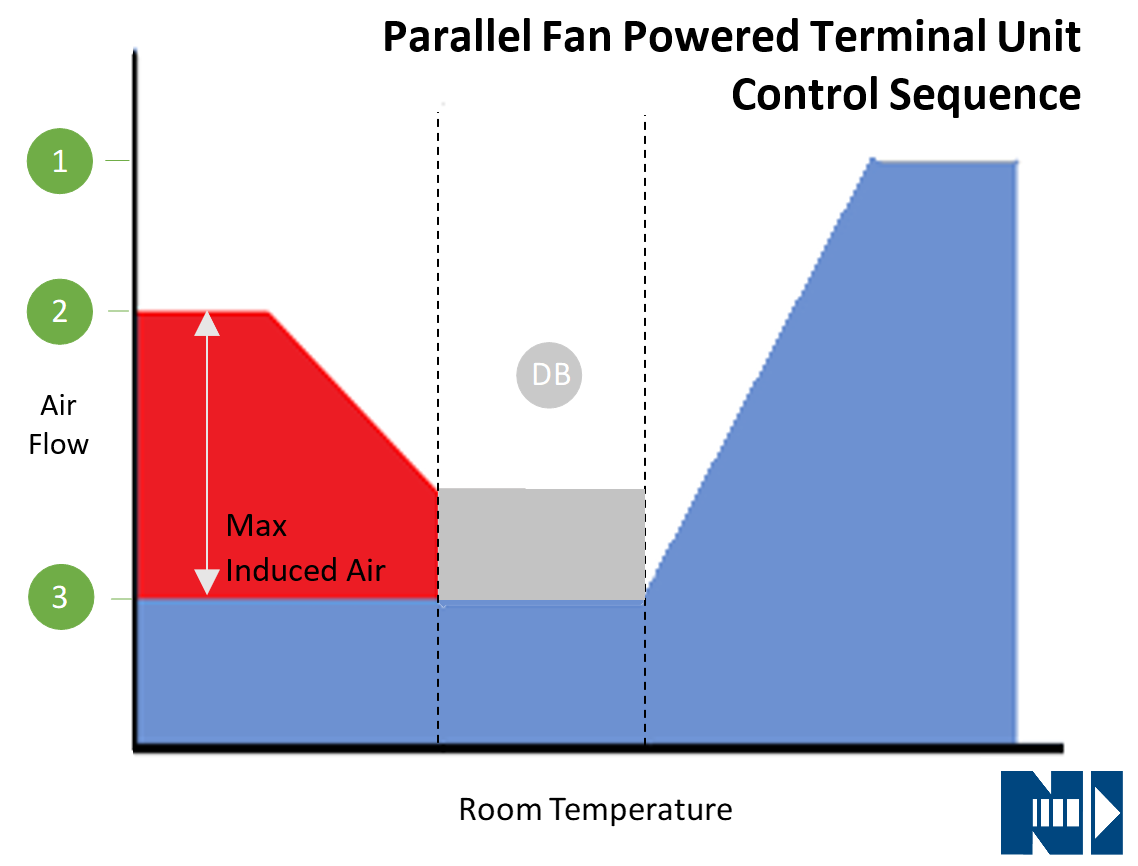
Fan Powered Terminal Units have been the standard design choice for most large commercial HVAC systems for many years. These units increase controllability of the system while reducing energy by maximizing the building diversity. The fan contained within the unit is able to induce air from the plenum for recapturing unvitiated air and providing warmer air to the heat source in deadband and heating zones. The two types of units are Series & Parallel and they have the control sequences shown below:
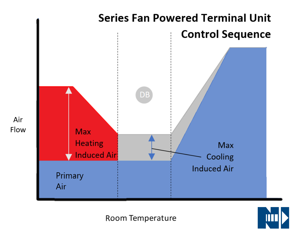

With series fan powered terminal units, the flow from the air handler and the fan is running at these set points depending on the call from the space thermostat. In part load conditions, the fan will induce flow from the air in the plenum. Even when there is no call for cooling or heating, during deadband mode, the fan will induce some plenum air to keep the mandatory primary air from overcooling the space.
Parallel fan powered terminal units have a fan that is outside the primary air supply and is only operational during the deadband and heating modes. When the terminal unit fan is operational it increases the static pressure required from the air handling unit fan to deliver the ventilation air to the space.
Induced Air
With these control sequences, even in the heating mode, the velocity of plenum air induced into the mixing chamber is very low. The air flow from the plenum is low enough to keep from inducing dust and particulate up into the air stream. For this reason, filters are not required by ASHRAE and not needed for the comfort of the space.
Fan Powered terminal units are typically provided to the job site with throwaway type fiberglass filters. These are designed to keep construction debris and particulate out of the unit during construction. The dirty filters shall be removed during the balancing operation and replaced with clean filters until the commissioning is completed when they should be discarded and not replaced
Difficulty with Filters
The goal of a fan powered terminal unit is to be maintenance free. If filters are left on the unit, more than likely they will be left there until a problem happens, sometimes years, possibly causing objectionable noise, increased energy consumption, and irreversible damage to the unit.
No Need for Filters During Normal Building Operations
With the low chance of dust circulation due to low air velocities and the increased chance of forgotten filters causing energy and comfort issues (including thermal and acoustical comfort), there is no reason for the fan powered terminal units to have filters during normal operation.
Understood, but I Still Want to Add a Filter, Can I?
The answer is, “It depends.”. It depends on the fan powered terminal unit, the fan it is using, the size of the filter, and the type of filter you would like to add to the unit.
Terminal Unit
Fan powered terminal units are designed to deliver a specific amount of air to the conditioned space to maintain the comfort for the occupants. This air is controlled by a fan, that is affected by the static pressure in the system. The fan motor’s ability is shown on a fan curve. For example, the fan curve below is for a Nailor 35S Size 5 series fan powered terminal unit.
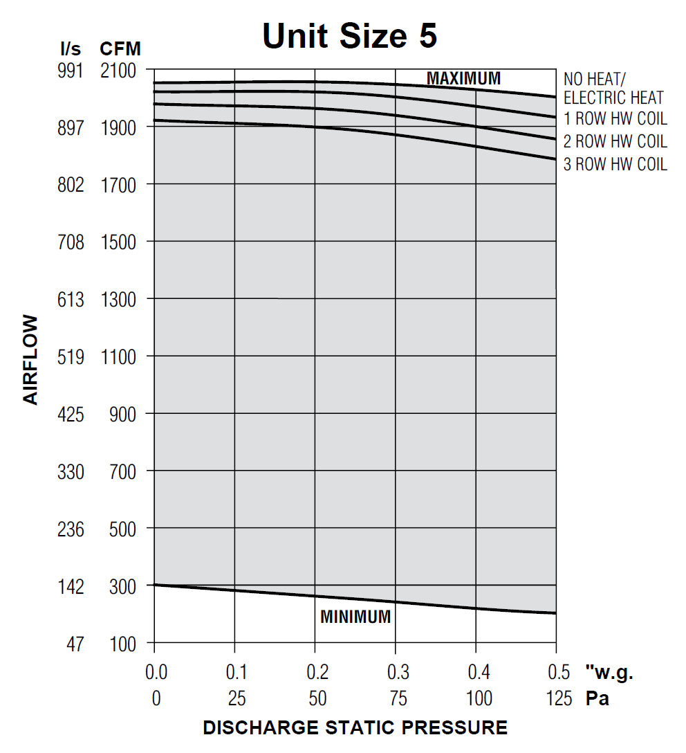
This shows the fan performance with various hot water coils and total static pressures. The discharge static pressure includes the discharge ducts, diffusers, room distribution requirement, as well as any filters upstream from the fan. This unit has an induction port that is 14” x 14”.
Filter
Filters separate particulates from the air as it passes through. As filters become more efficient and can filter small particles, the pressure to push air through them increases. The pressure drop across the filter also increases with the air velocity over the filter as well as the particulate load.
Analysis
Using the unit above, if we assume the max call for heating is 1,100 CFM and it has 400 CFM of primary air provided by the air handling unit, it will have 700 CFM coming through the induction port. This will generate an air velocity of 514 ft/min. At this velocity the static pressure generated by the clean unloaded filter will be as follows:

Most of the filters aren’t even rated for this high of a velocity and it wouldn’t be recommended. Even at 100 ft/min, the 1-2" HEPA filter would be .47”, which when combined with the static of the ductwork downstream from the unit, might put the system outside the range of the fan’s operation.
Solution?
One option would be to add a custom boot onto the unit that would allow you to add a larger filter, reducing the velocity across the filter and therefore the static pressure.
For example, you could install a modified “Q” Boot that ran the length of the unit. For the Nailor 35S Size 5 Discussed, this would increase the filter to 41”x27”.
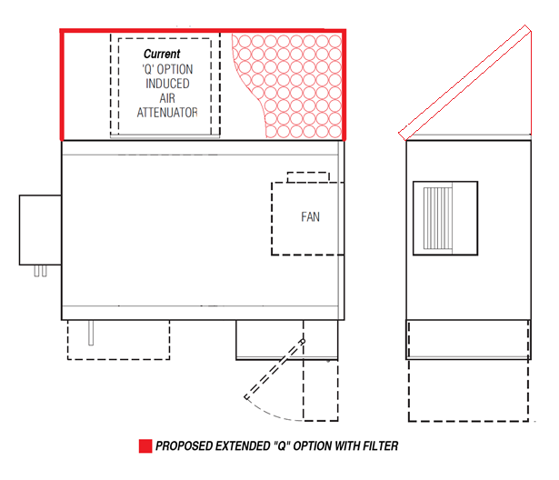
This would reduce the velocity across the filter to 197 ft/min, which would result in the following pressure drops.

If we assume the downstream ductwork in this example is only .15-.2” of static, the 2” MERV 13 could work in this application and the MERV 8 would be acceptable.
After working through this example, a 1-2" HEPA filter would almost never be acceptable to add to a terminal unit. 1-2" HEPA filters do not work above 150 ft/min face velocity.
Conclusion
Adding a filter that has greater efficiency than just a throwaway fiberglass filter can be done but could require modifications to the unit. Each individual unit’s size, design, and operating environment would have to be considered to determine the right route to take to ensure the performance of the unit is not compromised by the addition of the filter. Also, this analysis was done considering the initial pressure drop across the filter. As the filter is used and becomes “clogged” with filtrants the pressure drop will increase. This must be considered for replacement schedules depending on how much static pressure you have with the design of the unit.
Additional consideration would have to be given to the cost and potential problems associated with the requirement to change filters regularly if filters are added to the terminal units including:
- Access to the filter above the ceiling.
- Items below the access point, including desks, office furniture, and equipment that should not be exposed to the filter changing operations
- Floors and the required clean up after the ceiling is replaced
- Damaged Ceiling tiles
- Cost of labor and filters associated with this process
Nailor has been designing and manufacturing terminal units for over 25 years and is happy to work with you to meet the needs of your project. If you have any questions regarding terminal units, fan powered terminal units, and filter usage with any air side HVAC equipment please do not hesitate to reach out to us.